Table of Contents
An MC4 panel mount connector creates a fixed photovoltaic connection point through an inverter, combiner box or other equipment enclosure.
Unlike a standard cable-to-cable connector, one side of the connection is mechanically attached to the equipment itself. That makes the component more than a connector: it also becomes part of the enclosure interface.
Correct selection therefore involves four separate relationships:
External mating connector → panel-mounted interface → enclosure seal → internal conductor
If any one of these is poorly specified, the finished equipment connection can fail even when the connector’s headline voltage and current ratings appear suitable.
UHCCY uses Solar Connector and PV Connector for its own products; the phrase “MC4 panel mount connector” is used here because it is a common search term for this type of PV connection.
For available UHCCY configurations, see Solar Connector.
MC4 panel mount connector for photovoltaic equipment enclosuresWhat Is an MC4 Panel Mount Connector?
An MC4 panel mount connector—also commonly called a PV bulkhead connector or panel receptacle—is designed to create a detachable DC connection through a fixed equipment wall.
The connector body is mechanically secured to the enclosure while an external cable connector mates to the exposed interface.
On the equipment side, the electrical contact connects to the internal conductor or other specified termination.
The arrangement can be represented as:
External PV cable → detachable connector → fixed panel connector → internal equipment wiring
Stäubli similarly describes its PV panel receptacles as threaded panel-mounted interfaces used as string inputs for inverters and MLPE devices.
The generic terms panel mount, bulkhead and panel receptacle therefore refer to the mounting architecture, not to one universal connector design.
Panel-Mount vs Inline Solar Connector
A panel-mount connector and an inline connector may use a similar external mating interface, but they perform different mechanical functions.
| Feature | Panel-Mount Connector | Inline Connector |
|---|---|---|
| Mechanical position | Fixed to equipment | Supported by cable |
| Main purpose | Equipment interface | Cable-to-cable connection |
| Panel penetration | Yes | No |
| External side | Detachable mating connector | Detachable mating connector |
| Internal side | Equipment conductor / termination | Second cable |
| Enclosure sealing | Part of system design | Not normally applicable |
| Typical use | Inverter, combiner box, enclosure | Module/string wiring |
The important distinction is:
A panel-mount connector transfers the PV connection across an equipment boundary.
That changes both the mechanical and environmental design requirements.
It should therefore not be treated as an ordinary inline connector with a mounting nut added.
How a Panel-Mount Connector Works Across an Equipment Wall
A typical panel-mounted PV interface contains several functional zones.
External Mating Interface
This is the side accessible from outside the equipment.
It connects to the corresponding PV cable connector and provides the detachable interface used during installation or servicing.
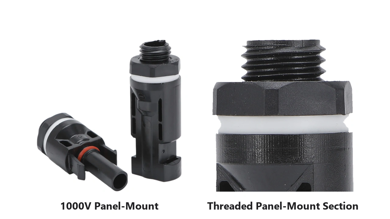
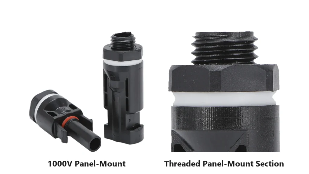
Panel-Mounting Section
A threaded or otherwise mechanically retained section fixes the connector body to the equipment wall.
Depending on the design, mounting components may include:
- threaded body;
- nut;
- washer;
- sealing element;
- locating features.
Internal Electrical Connection
Behind the panel, the connector must transition into the internal electrical circuit.
This can use a crimped conductor or another product-specific termination system.
The complete connection path is therefore:
PV cable → external connector contact → panel connector contact → internal conductor → equipment
This is why the internal termination deserves the same attention as the visible external connector.
Where Panel-Mount PV Connectors Are Used
Panel-mounted PV connectors are most useful where external photovoltaic wiring must connect to equipment while maintaining a defined removable interface.
Typical applications include:
PV Inverters
String inputs can be presented directly on the inverter enclosure so field cables connect without passing loose conductors through the housing.
PV Combiner Boxes
Panel connectors can provide defined string inputs or outputs through the enclosure wall.
MLPE and DC Equipment
Power electronics, monitoring devices and other PV equipment can use panel receptacles where a detachable outdoor connector is preferable to a permanent cable gland connection.
Junction and Interface Enclosures
A panel-mounted connector can create a transition between external PV cabling and protected internal wiring.
The important requirement is not the equipment name.
It is whether the design needs:
a fixed enclosure interface + detachable external PV connection.
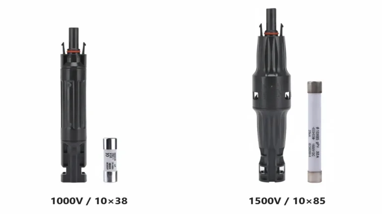
1000V vs 1500V Panel-Mount Connectors
System voltage remains one of the first selection parameters.
The panel-mounted connector must be suitable for the maximum DC voltage expected at that equipment interface.
Do not assume that two visually similar panel connectors have the same voltage rating.
For UHCCY, the current platforms illustrate this distinction:
| Model | Platform | Current Configuration | Conductor |
|---|---|---|---|
| UH-PC-PM01 | 1000V DC | 30A | 2.5 / 4 / 6 mm² |
| UH-PC-PM02 | 1500V DC | 30A / 45A / 50A | 2.5 / 4 / 6 mm² |
These are UHCCY product specifications, not universal industry values.
For PM02, the current-specific configurations are:
2.5 mm² → 30A
4 mm² → 45A
6 mm² → 50A
The broader principle is that:
Voltage platform, contact design and conductor configuration should be selected together.
For the system-level difference, see 1000V vs 1500V Solar Connectors.
Current, Conductor Size and Internal Termination
Panel mounting does not change the basic electrical requirement of a PV connector.
The contact and conductor must still be correctly matched.
Check:
Rated current → conductor cross-section → contact geometry → termination method
A common mistake is to focus only on the external mating connector while treating the equipment-side conductor as an afterthought.
But the internal termination is part of the same current path.
A poor crimp behind the enclosure can create the same high-resistance condition as a poor field connector outside it.
Internal Wire Size Should Not Be Assumed
The external PV cable and the internal equipment conductor may perform different functions and may not necessarily use identical construction.
The equipment manufacturer should verify:
- conductor cross-section;
- conductor construction;
- insulation requirements;
- temperature conditions;
- current capability;
- contact compatibility.
Do not select a panel receptacle only from the size of the external solar cable.
For connector/contact relationships, see MC4 Connector Specifications.
Panel Cutout, Thread and Mechanical Mounting
This is one of the most important differences between a panel connector and an inline connector.
The enclosure becomes part of the mechanical installation.
Selection may need to consider:
- mounting thread;
- panel opening;
- panel thickness;
- washer or seal position;
- retaining hardware;
- connector orientation;
- available internal clearance;
- available external clearance.
Do Not Use Thread Diameter as the Panel Cutout
A nominal threaded-section diameter does not automatically define the correct enclosure hole.
The required opening can depend on:
- actual thread geometry;
- locating features;
- seal dimensions;
- tolerance;
- mounting hardware.
For example, UH-PC-PM01 uses an M11.8 × 1.5 mounting thread, while the PM02 drawing shows an approximately 11.89 mm threaded section.
Those values describe the connector body.
They should not be converted directly into a production panel cutout without checking the dimensional drawing and required tolerances.
For an OEM enclosure, define the opening from the exact connector drawing before tooling or punching the panel.
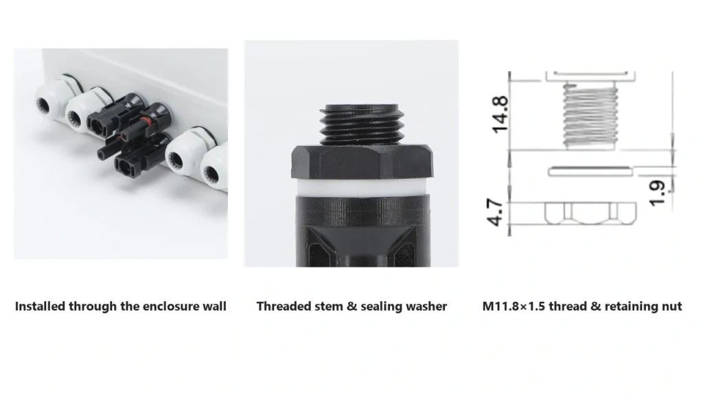
Panel mount solar connector threaded installation through an enclosureIP Rating and Enclosure Sealing Are Not the Same Thing
This is one of the most useful distinctions when specifying a panel-mounted connector.
A product may state:
IP67 when correctly installed and mated
but that does not automatically prove that the entire equipment enclosure remains IP67 after the connector is installed.
There are at least two environmental interfaces:
1. Connector mating interface
and:
2. Connector-to-panel interface
The first concerns sealing between the two mated connector halves.
The second concerns sealing where the fixed connector passes through the equipment wall.
A finished enclosure can therefore depend on:
- connector mating condition;
- mounting seal or washer;
- panel surface;
- panel opening accuracy;
- mounting compression;
- enclosure construction.
This leads to an important equipment-design principle:
Connector IP rating and enclosure IP performance are related, but they are not automatically the same claim.
For UH-PC-PM01 and PM02, the current product specification is IP67 when correctly installed and fully mated. The finished equipment manufacturer still needs to verify the complete panel interface for the required enclosure protection.
Polarity, Gender and Mating Compatibility
A panel-mounted connector is available in complementary contact/interface forms, but external appearance should not be used as the sole method of identifying polarity.
Keep three concepts separate:
connector interface
pin/socket contact
positive/negative circuit polarity
The required panel connector should be selected so that the completed equipment interface mates with the intended external cable while preserving the electrical polarity defined by the equipment design.
For the terminology problem, see MC4 Male vs Female Connectors.
Panel Mount Does Not Eliminate the Cross-Mating Problem
A panel receptacle is still part of a connector system.
Do not assume that an external connector from another manufacturer is acceptable because:
- it physically fits;
- it locks;
- both are described as MC4-type;
- both have the same nominal voltage;
- both use a Ø4 mm contact system.
Physical mating does not establish documented intermateability.
See MC4 Connector Compatibility before specifying a mixed connector interface.
For OEM equipment, this issue is particularly important because choosing a panel receptacle effectively defines the mating interface that installers will encounter in the field.
Installation and Serviceability
Panel-mounted connectors should be installed as both electrical and mechanical components.
A practical sequence is:
Select connector → verify panel drawing → prepare enclosure → mount connector → terminate internal conductor → verify retention and polarity → mate external connector → inspect complete interface
Mechanical Installation
Check that:
- the enclosure opening matches the drawing;
- the connector sits correctly against the mounting surface;
- sealing components are correctly positioned;
- retaining hardware is secure;
- the housing is not damaged by excessive tightening.
Do not apply a generic torque value from another connector brand or product family.
Use the value specified for the exact connector where a torque is provided.
Electrical Termination
For crimp-contact versions:
- use the correct contact;
- use the specified conductor size;
- prepare the conductor without damaged strands;
- use suitable crimp tooling;
- verify contact retention after assembly.
See How to Crimp MC4 Connectors for the general termination principles.
Service Space Matters
A connector can be electrically correct but difficult to maintain if the enclosure layout leaves insufficient space behind it.
OEM equipment designers should consider:
- access for crimping or assembly;
- conductor bend radius;
- clearance from terminals and busbars;
- future connector replacement;
- access to the retaining nut;
- safe separation from other internal circuits.
Serviceability should therefore be considered before the final panel layout is frozen.
How to Specify a Panel-Mount Solar Connector for B2B Purchasing
A request such as:
“Need 1500V panel MC4.”
is not enough for accurate quotation.
A useful RFQ should define:
| Requirement | What to Specify |
|---|---|
| Function | Panel-mount / bulkhead PV connector |
| System voltage | 1000V / 1500V / project requirement |
| Required current | Actual equipment current |
| Conductor size | mm² |
| Contact version | Required pin / socket interface |
| Mating counterpart | Exact external connector system |
| Mounting method | Threaded / model-specific |
| Panel drawing | Required cutout and wall interface |
| Enclosure protection | Required finished equipment IP level |
| Internal termination | Crimp or specified design |
| Contact plating | Standard or project requirement |
| Operating environment | Temperature / outdoor exposure |
| Certification | Exact project and market requirement |
| Quantity | Sample / production / annual demand |
| OEM requirements | Marking, packaging, documentation |
For UHCCY applications, the choice between:
UH-PC-PM01 – 1000V Panel-Mount Solar Connector
and:
UH-PC-PM02 – 1500V Panel-Mount Solar Connector
should start from the equipment voltage architecture, conductor/current requirement and mechanical enclosure design.
The connector should then be specified together with its approved mating interface.
Key Takeaway
A panel-mounted PV connector should be treated as an equipment interface, not simply as another cable connector.
The complete design path is:
External PV cable → mating connector → fixed panel interface → panel seal → internal termination → equipment
That produces several practical rules:
- Panel-mount and inline connectors perform different mechanical functions.
- Select the voltage platform from the actual PV equipment architecture.
- Match current, conductor size and contact configuration together.
- Do not define the panel hole from thread diameter alone.
- The enclosure wall and mounting hardware become part of the mechanical design.
- A mated connector IP rating does not automatically guarantee the finished enclosure IP rating.
- Internal conductor termination is part of the same electrical connection path.
- Male/female interface should not be confused with electrical polarity.
- Panel mounting does not make cross-mating between different connector systems acceptable.
- OEM designers should consider service clearance before finalizing the panel layout.
The better selection question is therefore not:
“Which panel connector fits this hole?”
It is:
“Which connector system creates the required electrical, mechanical and environmental interface between the external PV circuit and this equipment?”