Table of Contents
An MC4 diode connector integrates a blocking diode into an inline photovoltaic connection so current can pass in the intended direction while reverse current is restricted.
Its purpose is often misunderstood.
A blocking diode is not the same component as the bypass diodes normally found inside a PV module junction box, and installing an inline diode is not automatically required simply because solar panels are connected in parallel.
The correct selection process is:
Circuit purpose → reverse-current risk → diode orientation → current requirement → reverse-voltage requirement → thermal performance → connector compatibility
UHCCY uses Solar Connector and PV Connector for its own products; “MC4 diode connector” is used here because it is a common search term for this type of inline PV component.
For available diode-integrated and other photovoltaic connector configurations, see Solar Connector.
MC4 diode connector for solar PV reverse current blockingWhat Is an MC4 Diode Connector?
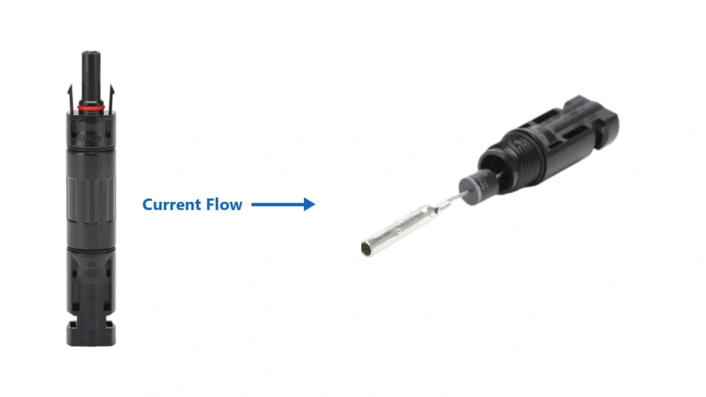
An MC4 diode connector is an inline PV connector containing a diode connected in series with the electrical path.
When installed in the correct orientation, the diode conducts normal photovoltaic current in one direction while restricting current attempting to flow in the opposite direction.
IEC 62548 defines a blocking diode as a diode connected in series with PV modules, strings, sub-arrays or arrays to block reverse current. The current edition of the PV array design standard is IEC 62548-1:2023+A1:2025.
Conceptually:
PV source → blocking diode → DC circuit
Normal current:
PV → load/inverter
Reverse current:
DC bus → diode ⛔ → PV string
The diode therefore controls current direction.
It does not act like a switch and it does not perform the same function as a fuse.
Blocking Diode vs Bypass Diode
This is the most important distinction in this topic.
Many online product pages use the terms blocking diode and bypass diode almost interchangeably. They are electrically different.
| Component | Connection | Main Function |
|---|---|---|
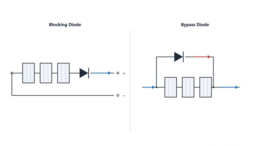
| Blocking diode | In series with PV circuit | Prevent reverse current |
| Bypass diode | Across cells or module section | Allow current to bypass shaded/faulted cells |
A blocking diode is part of the string current path.
A bypass diode normally sits across groups of cells inside the module junction box and becomes conductive when those cells are driven into reverse bias.
The two can be visualized as:
Blocking diode:PV String → Diode → Output
Bypass diode:Cell Group → with the diode connected around the cell group as an alternate current path.
So an inline diode connector should not be marketed as:
“a replacement for the solar panel bypass diode.”
That is normally the wrong function.
Solar blocking diode versus bypass diode wiring diagramWhy Reverse Current Can Occur in a PV Array
A photovoltaic source normally supplies current toward the inverter, charge controller or DC load.
But some circuit conditions can create a higher electrical potential elsewhere in the system and drive current back toward a PV string.
Examples can include:
- parallel PV strings operating under different conditions;
- a faulted string connected to healthy parallel strings;
- battery-connected systems where another device does not already prevent reverse current;
- other DC architectures containing multiple power sources.
IEC PV design guidance specifically recognizes blocking diodes as a method used to prevent reverse current in parts of an array.
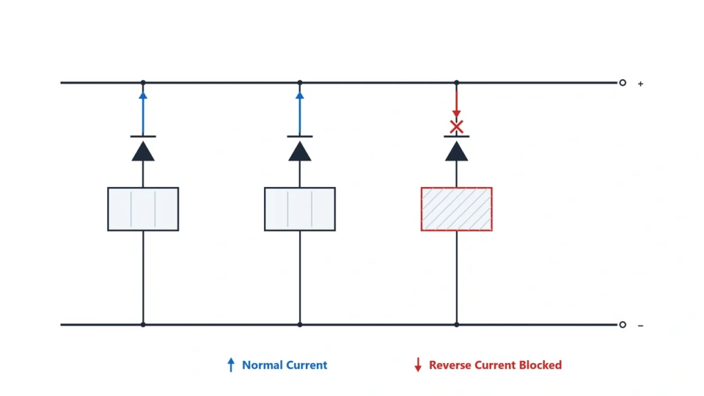
A simplified parallel-array example is:
String A ─┐String B ─┼→ Common DC BusString C ─┘
If String A develops an appropriate fault or its voltage falls sufficiently relative to the common bus, Strings B and C can contribute current toward that branch.
A correctly selected blocking diode in series with String A can prevent that reverse-current path.
PV blocking diode preventing reverse current from parallel solar stringsDoes Every Solar System Need a Blocking Diode?
No.
The existence of a diode connector does not mean every PV string should contain one.
Whether a blocking diode is useful depends on the actual circuit architecture and the protection already provided by other equipment.
For example, a system may already use:
- string overcurrent protection;
- inverter input circuitry;
- charge-controller reverse-current protection;
- DC/DC conditioning equipment;
- another system-level reverse-current control method.
Adding an unnecessary blocking diode introduces additional:
voltage drop → power dissipation → heat → electrical interfaces
Therefore:
Use a blocking diode because the electrical design requires reverse-current blocking, not simply because one can be inserted into the connector path.
For systems containing batteries, also verify whether the charge controller or other power electronics already provides nighttime reverse-current protection before adding another series diode.
Blocking Diode vs Inline Fuse
A diode connector and a fuse connector solve different electrical problems.
Diode Connector
Controls direction of current.
Normal current can continue flowing through the diode.
Reverse current is blocked when the diode is operating correctly.
Fuse Connector
Provides overcurrent protection.
When sufficient fault current operates the fuse, the fuse opens the circuit.
The functional difference is:
Blocking diode → prevents current from flowing the wrong way
Fuse → interrupts excessive current
A blocking diode therefore should not automatically be treated as a substitute for the string fuse required by a particular design or local electrical rule.
If overcurrent protection is the main requirement, see the MC4 Inline Fuse Guide.
Current Rating Is Only Part of Diode Selection
A diode connector must carry the intended forward current without excessive electrical or thermal stress.
UHCCY’s current UH-PC-MD01 range provides:
10A / 15A / 20A / 30A
versions at 1000V DC.
These are separate current configurations, not a statement that one generic diode automatically supports any current from 10A to 30A.
The selected version should be coordinated with the actual PV circuit.
Important current-related inputs include:
- module or string operating current;
- short-circuit current;
- applicable design factor;
- ambient temperature;
- expected continuous duty;
- diode manufacturer limits.
Do not select the diode only from module wattage.
Two PV systems with the same wattage can operate at very different voltage and current levels.
Reverse Voltage Matters as Much as Current
Blocking diodes experience two very different electrical conditions.
In the forward direction they must carry the normal PV current.
In the reverse direction they must withstand the voltage attempting to drive current backward.
That means diode selection involves at least:
Forward-current capability
and:
Reverse-voltage capability
These are semiconductor parameters and should not be confused with the headline connector voltage alone.
For example:
A connector housing marked 1000V DC does not by itself prove the internal diode semiconductor has every reverse-voltage characteristic required for every possible 1000V PV application.
The exact diode data and complete product qualification matter.
For UH-PC-MD01, the currently published product specification gives the connector system voltage as 1000V DC, but the individual diode forward-voltage and reverse-voltage parameters are currently listed as not specified on the product page.
For projects where semiconductor-level diode data is part of the engineering approval, request the exact diode specification rather than inferring it from the connector’s 1000V designation.
This is especially important in OEM and engineered PV projects.
Forward Voltage Creates Heat and Power Loss
A real diode is not an ideal one-way switch.
When it conducts, it has a forward voltage drop.
Its approximate conduction loss is:
P ≈ Vf × I
where:
P = diode power dissipation
Vf = forward voltage at the operating condition
I = current through the diode
For example, increasing circuit current increases the heat that must be dissipated by the diode assembly.
This is why a diode connector must be evaluated thermally, not only electrically.
Relevant factors include:
- diode forward voltage;
- operating current;
- ambient temperature;
- enclosure construction;
- heat transfer through the connector body;
- continuous operating duration.
IEC PV design guidance specifically includes heat-dissipation design for blocking diodes as part of blocking-diode selection.
This leads to an important procurement point:
“30A diode connector” does not mean thermal performance can be judged from the 30A label alone.
Forward-voltage and temperature data are valuable whenever the application operates close to the diode’s continuous rating.
Installation Direction and Polarity Matter
A blocking diode is directional.
If the connector is installed backward, it can block the current that the PV system is supposed to deliver.
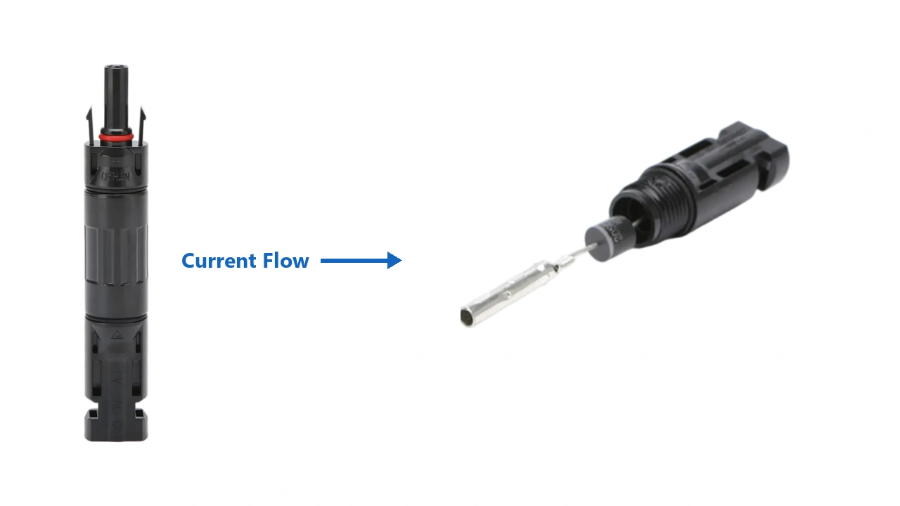
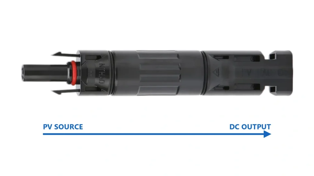
UH-PC-MD01 therefore requires installation according to the specified current-flow direction. Its product instructions explicitly warn that reversing the diode orientation will block the intended forward current path.
Do not determine installation direction only from:
- male/female housing appearance;
- cable color;
- assumptions about which polarity normally receives a diode.
Instead verify:
PV source side → intended current-flow direction → load/bus side
and follow the product marking or installation drawing.
The electrical polarity of the circuit and the mechanical gender of a connector remain separate concepts.
See MC4 Male vs Female Connectors for the full explanation.
Solar diode connector correct current flow directionConnector Compatibility Still Applies
Adding a diode does not turn the connector into a universal interface.
The external connector interfaces still have to form a valid mating system.
Do not assume the diode connector is suitable because:
- both interfaces appear MC4-shaped;
- the housings physically lock;
- the current ratings are similar;
- both products are marked 1000V.
The same compatibility principles apply as with an ordinary inline connector:
contact geometry + mating force + materials + sealing + locking + documented mating combination
For mixed connector systems, see MC4 Connector Compatibility.
This point matters even more with a functional connector such as an inline diode because the assembly now contains:
connector interface → semiconductor → connector interface
rather than only a basic conductor-to-conductor contact path.
How to Specify a PV Diode Connector
For B2B purchasing, a request such as:
“Need 20A MC4 diode.”
is incomplete.
A useful specification should define:
| Requirement | What to Specify |
|---|---|
| Function | Series blocking / reverse-current blocking |
| System voltage | Required PV DC voltage |
| Current | Required continuous operating current |
| Reverse-voltage requirement | According to circuit design |
| Diode data | Vf / VRRM or other required semiconductor parameters |
| Installation direction | Source and output orientation |
| Connector system | Required mating interface |
| Cable configuration | If cable leads are included |
| Protection degree | Required environmental rating |
| Ambient temperature | Project condition |
| Certification | Exact required product documentation |
| Quantity | Sample / production |
| OEM requirement | Model marking / packaging / drawing |
UH-PC-MD01 currently provides:
- 1000V DC
- 10A / 15A / 20A / 30A
- IP67 when correctly mated
- -40°C to +85°C ambient range
- tin-plated copper contacts as standard
- silver-plated copper contacts available on request
while semiconductor forward-voltage and reverse-voltage values are not currently published.
For applications where these parameters determine thermal or protection design, obtain them before final model approval.
Common Diode Connector Mistakes
The most common errors are not usually mechanical.
They are conceptual.
Confusing Blocking and Bypass Diodes
A series blocking diode prevents reverse current.
A module bypass diode provides an alternate path around cells or cell groups.
They are not interchangeable.
Adding a Diode to Every PV System
A diode should solve an identified reverse-current problem.
Unnecessary diodes add loss and heat.
Selecting Only by Amperage
Current rating does not describe reverse-voltage capability or forward-voltage loss.
Installing the Diode Backward
A reversed blocking diode can prevent normal PV output.
Assuming the Diode Replaces a Fuse
Current direction control and overcurrent interruption are different protection functions.
Ignoring Heat
The diode continuously dissipates power whenever forward current flows.
Assuming Every “MC4” Interface Is Compatible
Physical fit remains insufficient evidence of a documented mating system.
Key Takeaway
A diode-integrated PV connector should be selected as both a connector and a semiconductor protection component.
The useful design sequence is:
Need for reverse-current blocking → circuit current → reverse voltage → diode loss and temperature → installation direction → connector mating system
Remember:
- A blocking diode is installed in series to prevent reverse current.
- A bypass diode is a different component with a different circuit function.
- Not every PV system automatically requires an external blocking diode.
- A diode connector does not automatically replace required overcurrent protection.
- Diode current rating and connector voltage rating are not the only parameters that matter.
- Reverse-voltage capability must suit the actual circuit.
- Forward voltage creates continuous power loss and heat.
- Installation direction is critical.
- Connector mating compatibility still has to be verified.
- For engineered projects, request semiconductor-level diode data when the published connector specification does not provide it.
The better purchasing question is therefore not:
“Which amperage diode connector should I buy?”
It is:
“Why does this PV circuit require reverse-current blocking, and which diode-and-connector assembly can perform that function safely under the actual current, voltage and temperature conditions?”