Table of Contents
Two photovoltaic connectors can look identical, lock together with an audible click and still not be a verified mating pair.
That is the central issue behind MC4 connector compatibility.
In the market, terms such as “MC4 compatible,” “MC4 type” and “MC4 style” are frequently used to describe connectors with a familiar PV interface. But physical similarity does not prove that two products from different manufacturers have been designed, tested or certified to operate together.
A more useful way to evaluate PV connector compatibility is to ask five separate questions:
Do they physically mate?
Do the contacts mate correctly?
Can the connection carry the required electrical load?
Does the complete pair maintain its environmental protection?
Is that exact mating combination documented or approved for the project?
Only after all five questions have been answered should a connector pair be treated as an intentional connection system.
UHCCY therefore uses Solar Connector and PV Connector for its own connector products.
For basic MC4 terminology first, see the MC4 Connector Guide.
What Does MC4 Compatible Actually Mean?
There is no useful universal interpretation of the phrase “MC4 compatible” without additional documentation.
Depending on the seller, it may mean:
- the connector looks similar to an MC4
- the locking geometry is similar
- the connector can physically mate with another product
- the supplier has tested a particular combination
- a particular mating pair has formal intermateability documentation
Those claims are not equivalent.
This is why a product description saying:
“MC4 compatible, 1500 V, 50 A”
still does not tell a buyer which exact connector it is intended to mate with.
For procurement, the more useful question is:
Which manufacturer, series and model is this connector documented to mate with?
Compatibility Has More Than One Level
The word compatibility is often treated as yes/no.
For PV connectors, it is better understood in layers.
| Compatibility level | Question | Why it matters |
|---|---|---|
| Physical fit | Can the housings plug together? | Only proves gross mechanical similarity |
| Mechanical interface | Do locking and retention features engage correctly? | Affects retention and connector stability |
| Contact interface | Do pin/socket geometry and contact forces match? | Affects resistance and heating |
| Environmental interface | Do seals and mating surfaces work together? | Affects moisture and dust protection |
| Electrical rating | Is the pair suitable for voltage/current conditions? | Affects operating safety |
| Intermateability documentation | Is the exact mixed combination permitted or evaluated? | Determines whether the connection is intentionally supported |
A connector pair can pass the first test and fail the later ones.
That is why:
“It clicks together” is not a compatibility certificate.
Why Two Similar PV Connectors Can Still Be Different
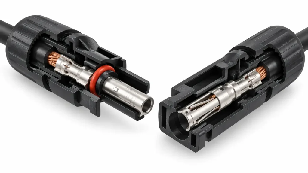
Small differences are difficult to see from the outside.
The most important variations can be inside the connector.
Contact Diameter and Geometry
The conductive pin and socket form the electrical interface.
Even where nominal dimensions appear similar, manufacturers can use different:
- tolerances
- contact profiles
- spring structures
- mating depths
- contact pressure systems
The housing can therefore latch while the internal contact interface does not behave exactly as intended.
Contact Spring Force
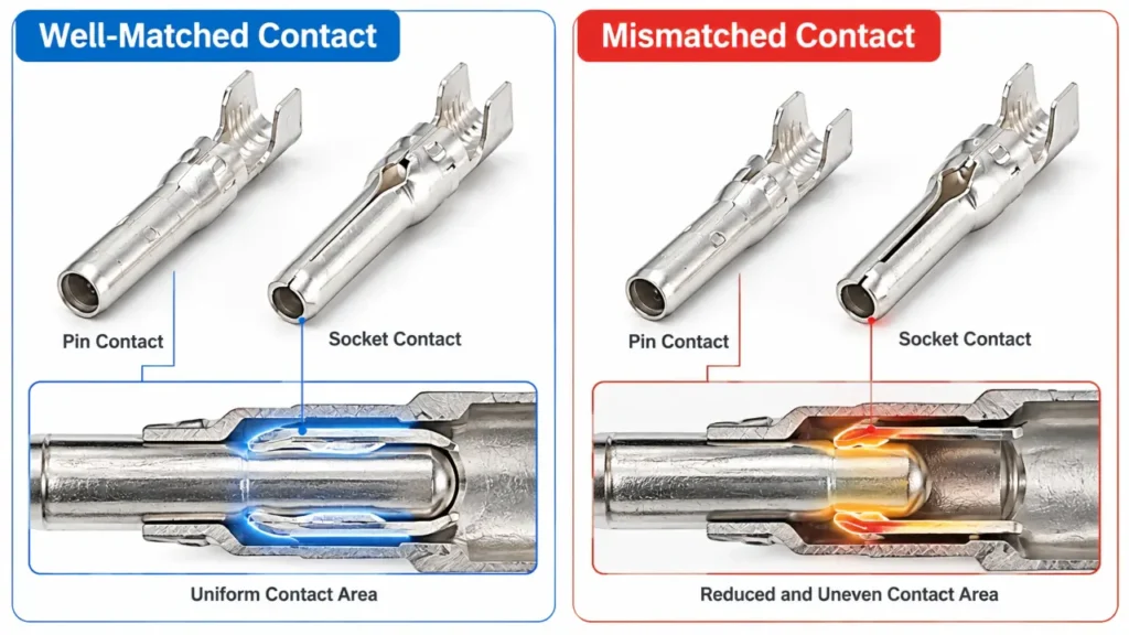
The electrical connection depends on sufficient contact force.
If the contact interface is too loose, contact resistance can increase.
If the geometry is excessively tight or mismatched, insertion can damage the contact or alter its intended mechanical behavior.
This is one reason connector compatibility cannot be assessed by housing dimensions alone.
Contact Material and Plating
PV connector contacts may use tin-plated copper, silver-plated copper or another documented contact system depending on product design.
Different contact materials and surface finishes should not simply be assumed to behave identically when combined.
The complete contact pair needs to be treated as part of one electrical interface.
Seal Geometry
A mated PV connector normally relies on carefully controlled sealing surfaces.
A housing that appears identical externally may use different:
- seal dimensions
- compression characteristics
- mating depths
- polymer tolerances
Therefore an individual connector’s IP rating does not automatically transfer to an arbitrary cross-mated combination.
Locking Features
Locking tabs may engage well enough to make a click but still differ in:
- engagement depth
- retention force
- release geometry
- dimensional tolerance
Again, physical engagement alone does not prove the connection has been evaluated as a system.
What Is Cross-Mating?
Cross-mating means connecting mating connector halves from different connector systems or manufacturers.
For example:
Manufacturer A plug + Manufacturer B socket
rather than:
Manufacturer A plug + Manufacturer A’s documented mating socket.
The terms cross-connection, cross-mating and intermateability are all used in the PV industry when discussing this issue.
Intermateability is the more important concept.
It asks whether two different connector products are documented and evaluated as a valid mating pair—not merely whether they can be physically pushed together.
What IEC Says About Connector Incompatibility
This problem is sufficiently significant that IEC published an entire technical report specifically about it:
IEC TR 63225 — Incompatibility of connectors for DC-application in photovoltaic systems.
The report addresses the problems created when DC PV connectors produced by different manufacturers are combined and discusses recommendations for dealing with those incompatibilities.
The official publication is available from IEC TR 63225.
The important lesson for installers and buyers is not that every different-brand combination will immediately fail.
It is that:
different-manufacturer PV connector combinations should not be assumed compatible without evidence for that exact connection.
Stäubli’s Position on Original MC4 Cross-Mating
Stäubli takes a particularly clear position regarding Original MC4 products.
The company states that it does not recognize third-party products as compatible with its Original MC4 portfolio and advises against cross-connecting PV connectors from different manufacturers.
Its explanation also points to the fact that connector certification applies to defined products and mating systems rather than every product that can physically fit the interface.
Stäubli’s detailed position can be read on its PV connector cross-connection guidance.
This has an important implication for UHCCY terminology.
UHCCY should not describe one of its own products simply as:
“Original MC4 compatible”
unless there is specific documentation supporting the exact claimed mating relationship.
Instead, the UHCCY product should be specified by its own:
- model
- ratings
- contact configuration
- cable range
- intended mating counterpart
Available UHCCY connector configurations are organized under Solar Connector.
Does IEC 62852 Mean Two Certified Connectors Can Be Mixed?
No.
This is an important misunderstanding.
IEC 62852 defines safety requirements and tests for DC connectors used in photovoltaic systems.
It does not turn all connectors tested to IEC 62852 into one universal interchangeable interface.
Consider two connectors:
Connector A: tested or certified according to IEC 62852
Connector B: also tested or certified according to IEC 62852
That tells you something about each defined connector system.
It does not automatically establish:
Connector A plug + Connector B socket = certified mating combination.
The connector pair still needs to be evaluated according to the relevant product and installation requirements.
In other words:
same standard does not mean same mating system.
The same logic applies to many electrical products.
Two circuit breakers can comply with the same product standard without having interchangeable terminals or accessories.
PV connectors should be treated with the same engineering discipline.
What About UL 6703 and the U.S. Market?
For the North American market, UL 6703 is a key product standard for PV connectors.
The National Electrical Code also addresses mating connectors in PV systems.
The practical requirement for installers and buyers is straightforward:
do not assume cross-brand intermateability.
For U.S. projects, determine whether the intended mating connectors are:
- identical type and brand as required by the applicable installation rules, or
- specifically listed and identified for intermateability where permitted
The exact project requirements should be checked against the applicable edition of NEC and the connector manufacturers’ documentation.
This is particularly important when modules arrive at a project with factory-installed connectors from one manufacturer while field wiring uses another connector system.
Changing only one half of the connection can create a mixed-brand interface that was never part of the original procurement specification.
Same Brand Does Not Always Mean Every Series Is Compatible
There is another shortcut worth avoiding:
“They are made by the same manufacturer, so they must all work together.”
That is not a safe universal assumption either.
One manufacturer can offer multiple generations or families with different:
- ratings
- locking designs
- contact systems
- tooling
- cable ranges
- intended mating combinations
Therefore, even within one brand, verify the exact series and model.
A documented compatible combination is stronger evidence than a shared logo.
This distinction is especially important when:
- replacing an older module connector
- servicing legacy PV arrays
- changing from a 1000 V to 1500 V connector family
- mixing older and newer connector generations
For rating differences, see MC4 Connector Specifications.
Are T4 Connectors Compatible With MC4?
This is a good example of why compatibility should not be answered with a generic yes or no based on product family names.
“T4” and “MC4” refer to different manufacturer-specific connector systems.
A search result, distributor listing or successful physical mating does not provide enough evidence to establish that every T4 connector can be cross-mated with every Original MC4 connector.
Instead, verify:
- the manufacturer of the T4 connector
- the exact model/series
- the exact MC4 product it would mate with
- whether the manufacturer documentation identifies that combination
- the certification/listing basis required by the project
The same method applies to:
H4 vs MC4
PV4 vs MC4
SMK vs MC4
and other connector-family comparisons.
This is more reliable than maintaining a simplistic internet table saying:
Compatible / Not Compatible
because connector products and certification scopes can change over time.
What About “Universal MC4 Connectors”?
Be cautious with the word universal.
A universal connector would imply that one product can be used as a verified mating partner across a broad range of independent connector systems.
That is a much stronger claim than:
similar interface
or:
commonly described as MC4 type.
For B2B purchasing, ask a supplier who claims universal compatibility:
Which exact mating connector manufacturers and models are covered by your documentation?
If the answer is simply:
“All MC4 connectors.”
that is not sufficiently specific for professional procurement.
Why Cross-Mating Can Increase Contact Resistance
A PV connector works by creating a controlled metal-to-metal contact interface.
The effective resistance of the connection depends on factors including:
- contact geometry
- contact pressure
- contact surface condition
- crimp quality
- conductor size
- temperature
- aging
If mismatched contacts create a smaller or less stable effective contact area, connection resistance can increase.
Electrical power converted to heat at a resistive connection follows:
P = I²R
This relationship matters because heating rises with the square of current.
A small increase in resistance can therefore become increasingly significant in a high-current connection.
For example, if one connection develops additional resistance, the problem may not immediately appear as an open circuit.
The system can continue operating while that connection runs hotter than surrounding connectors.
That is why connector problems are often associated with:
- discoloration
- melted polymer
- damaged contacts
- localized heating
- eventual arcing
The correct response is not to assume that every overheated connector was caused by cross-mating.
Other causes include poor crimping, damaged contacts, incomplete assembly and overload.
But connector incompatibility is one of the factors that should be investigated.
For termination quality, see How to Crimp MC4 Connectors.
IP67 or IP68 on Both Connectors Does Not Prove the Pair Is IP67 or IP68
This is another common procurement mistake.
Suppose:
Connector A = IP68 when properly mated with Connector A counterpart
and:
Connector B = IP68 when properly mated with Connector B counterpart
That does not prove:
Connector A + Connector B = IP68
because the sealing interface itself has changed.
The IP rating applies under defined conditions to a tested product configuration.
When the mating combination changes, assumptions about:
- seal compression
- housing overlap
- locking position
- gasket contact
may no longer be valid.
For this reason, environmental compatibility should be evaluated at the mated-pair level, not simply by reading the individual connector labels.
A Continuity Test Does Not Prove Connector Compatibility
Another tempting shortcut is:
“I connected the two brands, measured continuity and everything works.”
A continuity test can confirm that an electrical path exists.
It does not verify:
- long-term contact resistance
- thermal performance
- sealing
- mechanical retention
- accelerated aging
- certification
- project compliance
Similarly, measuring normal voltage through the connection does not establish long-term compatibility.
The question is not simply:
Does electricity pass through it today?
The question is:
Was this connection designed and documented to perform reliably under the intended PV operating conditions over time?
How to Check an Existing Solar Array for Mixed Connectors
Existing installations can be more difficult because connector identification may not have been recorded.
Use a systematic inspection rather than assuming every black connector belongs to one family.
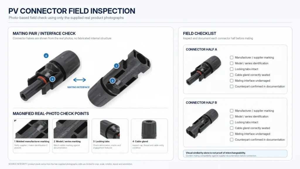
1. Check Housing Markings
Look for:
- manufacturer name
- trademark
- model or series
- approval markings
- molded identification
Do not rely only on housing shape.
2. Check Both Halves of Each Connection
Identifying one connector is not enough.
The actual question is:
What is it mated to?
Record both sides.
3. Review Module Documentation
Factory-installed module connectors may be identified in:
- module datasheet
- installation manual
- product label
- bill of materials
- certification documentation
4. Review Previous Repairs
Cross-mating often enters a system during later maintenance.
A technician may replace a damaged connector with whichever visually similar connector is available.
The result can be:
original factory connector + unrelated replacement connector
even if the rest of the installation is consistent.
5. Inspect for Thermal or Mechanical Damage
Look for:
- discoloration
- softened or melted housings
- cracked locking tabs
- partially mated connectors
- damaged seals
- corrosion
- cable movement
- abnormal temperature during appropriate inspection procedures
These signs do not prove cross-mating, but they justify further investigation.
What Should You Do if Different Connector Brands Are Already Mated?
Do not immediately assume the connection must be cut apart without first understanding the system.
Instead:
Identify Both Products
Determine the exact manufacturer and model of each connector half.
Check the Documentation
Look for manufacturer instructions, certification information and project documentation addressing the mating combination.
Check the Project Requirements
The acceptance criteria can vary according to:
- installation country
- applicable code
- project specification
- authority having jurisdiction
- product certification
Replace the Connection if Necessary
Where the combination is undocumented or unacceptable for the project, the corrective strategy normally involves restoring a defined connector system.
That may require replacing one or both connector halves using the correct:
- connector
- contact
- cable range
- crimp tool
- assembly process
Do not create a second compatibility problem while correcting the first one.
The wiring polarity must also be maintained correctly during replacement. See the MC4 Connector Wiring Guide.
What Should Buyers Request From a Connector Supplier?
For B2B procurement, compatibility should become a documentation question.
Instead of asking:
“Is this MC4 compatible?”
ask:
| Procurement question | Why it matters |
|---|---|
| What is the exact connector model? | Defines the actual product |
| What is the mating counterpart? | Defines the intended connection |
| Which contact belongs to the housing? | Prevents component mixing |
| What cable sizes and ODs are supported? | Defines termination and sealing |
| What voltage/current ratings apply? | Defines electrical capability |
| What standard/certificate covers the model? | Allows documentation verification |
| Is cross-brand mating claimed? | Identifies potential intermateability issue |
| If yes, which exact model combination? | Prevents broad “universal” claims |
| What evidence supports the claim? | Allows engineering review |
| Which crimp tool and die are specified? | Controls field/production termination |
This changes compatibility from a marketing word into a verifiable purchasing requirement.
For OEM Cable Assemblies, Standardize the Whole Connection
The simplest way to reduce connector-mixing risk in repeat production is to define the complete cable assembly.
Instead of purchasing:
PV cable
contacts
connector housings
from unrelated specifications, define:
Cable + Contact + Connector + Tooling + Mating Counterpart
as one controlled system.
For an OEM assembly, a useful specification includes:
- cable manufacturer/type
- conductor cross-section
- cable OD
- connector manufacturer
- connector series/model
- contact model
- end-A connector
- end-B connector
- polarity
- assembly tooling
- inspection criteria
- labeling/traceability
This is especially useful for:
- extension cables
- module leads
- combiner-box harnesses
- inverter leads
- custom OEM cable assemblies
Should UHCCY Call Its Products “MC4 Compatible”?
As a general product-description strategy, it is better not to use MC4 compatible as an unsupported blanket statement.
A clearer UHCCY product description is:
Solar Connector
or:
PV Connector
followed by the actual technical characteristics:
1500 V DC
6 mm²
specified current
specified cable OD
specified mating counterpart
This provides the buyer with information that can actually be verified.
“MC4” can still be discussed in educational content because it is a widely searched connector family and an important part of the PV market.
But UHCCY should not imply that its products are Original MC4 products or approved cross-mating partners without specific documentation establishing that relationship.
For available configurations, see Solar Connector.
A Practical Compatibility Decision Process
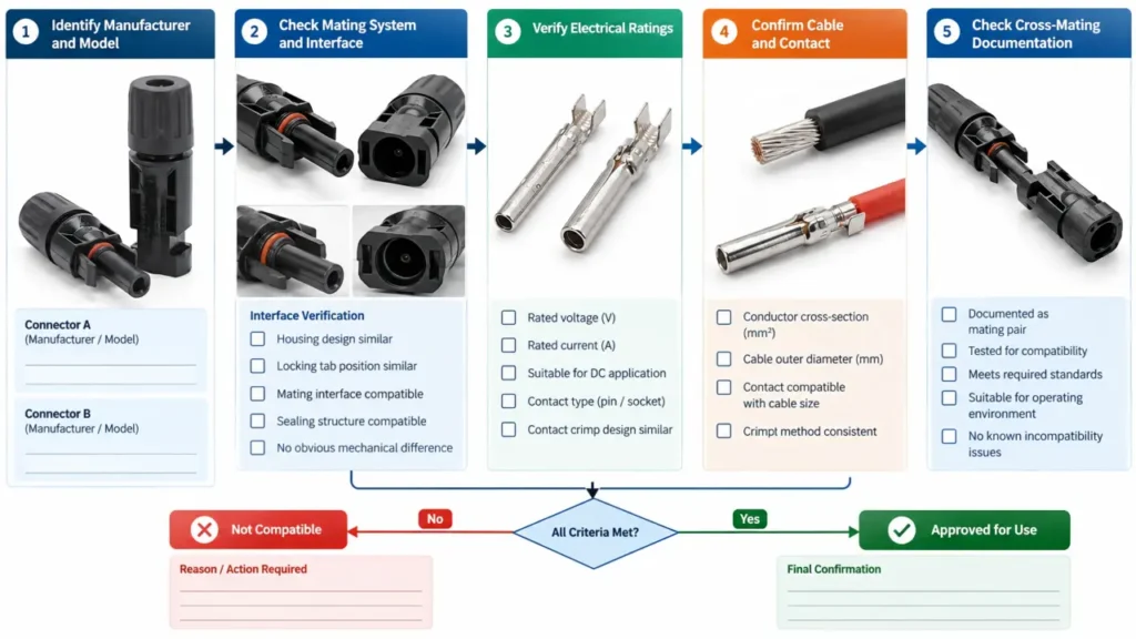
When evaluating any proposed PV connector pair, use this sequence.
Step 1: Identify Both Connectors
Record:
Manufacturer A + exact model
and:
Manufacturer B + exact model
If either connector cannot be identified, compatibility has not yet been established.
Step 2: Confirm the Intended Mating Pair
Check whether the connector manufacturers specify those exact halves as mating counterparts.
Step 3: Verify Electrical Ratings
Check:
- voltage
- current
- conductor size
- temperature
- applicable certification
Step 4: Verify Cable and Contact Configuration
Confirm:
- contact model
- conductor cross-section
- cable OD
- termination method
Step 5: Verify Environmental Performance
Do not transfer an IP rating from one mating configuration to another without supporting documentation.
Step 6: Verify Project Compliance
For North American installations, check the applicable NEC/listing requirements.
For IEC-based projects, check the applicable PV installation requirements and certification documentation.
Step 7: If Evidence Is Missing, Do Not Assume
A connector that physically fits has demonstrated only:
physical fit.
Nothing more.
Key Takeaway
MC4 connector compatibility cannot be determined by appearance alone.
The useful hierarchy is:
Physical fit
↓
Mechanical interface
↓
Electrical contact
↓
Environmental sealing
↓
Documented intermateability
A connector pair should not skip directly from:
“they click together”
to:
“they are compatible.”
For installation and procurement, remember:
- MC4 is not a generic certification for all similar PV connectors.
- Two connectors tested to the same product standard are not automatically interchangeable.
- Individual IP ratings do not automatically prove the mixed pair maintains that IP rating.
- Same brand does not automatically mean every product generation or series can be mixed.
- A continuity test proves an electrical path, not long-term compatibility.
- Cross-brand claims should identify exact manufacturer and model combinations.
- For repeat procurement, standardize the complete cable/contact/connector system.
- When documentation is missing, physical fit should not be treated as proof of compatibility.
A PV connector is a small component, but the correct engineering unit is the complete mated connection, not either connector half by itself.