Table of Contents
MC4 Connector Wiring Guide: Series, Parallel, Polarity & Branch Connections
MC4 connector wiring is often explained as a simple matter of plugging one solar-panel lead into another.
Mechanically, that may be true. Electrically, the important part is what the connection does to the array voltage, current, polarity and fault-current path.
A series connection increases string voltage. A parallel connection increases available current. A series-parallel array does both.
The connector itself does not decide whether the circuit is correct.
A reliable PV connection requires the connector, cable, module ratings, inverter or power-conversion input limits, polarity and protection design to work together.
MC4 is a protected trademark of Stäubli. UHCCY uses Solar Connector or PV Connector for its own connector platforms.
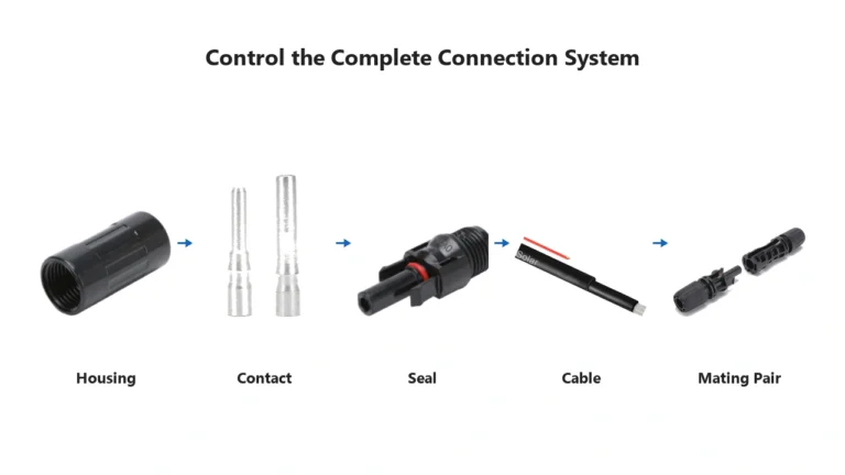
For the terminology and basic connector structure, see the MC4 Connector Guide.
MC4 Wiring Starts With the Electrical Topology
Before selecting a connector or branch adapter, determine what the PV circuit needs to do.
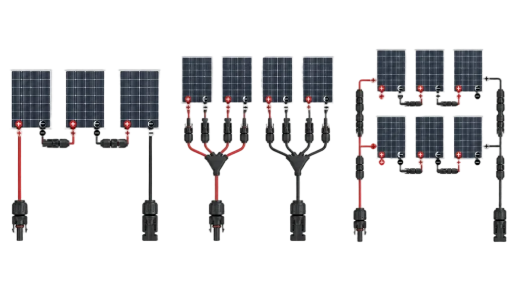
There are three basic arrangements:
| Wiring topology | Array voltage | Array current | Common connection method |
|---|---|---|---|
| Series | Voltages add | Approximately one string current | Direct module-to-module connection |
| Parallel | Approximately one string voltage | String currents add | Branch connector or combiner |
| Series-parallel | Series voltage × parallel strings | Current of parallel strings adds | Series strings combined in parallel |
Those rules assume suitably matched modules and normal operating conditions.
Real system design also needs to consider:
- open-circuit voltage (Voc)
- voltage at maximum power (Vmp)
- short-circuit current (Isc)
- current at maximum power (Imp)
- temperature effects
- inverter or MPPT input limits
- cable ampacity
- connector current rating
- overcurrent protection requirements
The connector is therefore part of the circuit design—not a substitute for it.
Understanding Voc, Vmp, Isc and Imp Before Wiring
Four module ratings are particularly important when planning PV wiring.
| Rating | Meaning | Mainly affects |
|---|---|---|
| Voc | Open-circuit voltage | Maximum possible string voltage |
| Vmp | Voltage at maximum power | Normal MPPT operating voltage |
| Isc | Short-circuit current | Circuit and protection calculations |
| Imp | Current at maximum power | Normal operating current |
These values should not be mixed together.
When modules are wired in series, voltages add.
When matched strings are wired in parallel, currents add.
This distinction is more useful than simply saying:
“Series increases voltage and parallel increases amps.”
The actual design checks use Voc, Vmp, Isc and Imp for different purposes.
How MC4 Connectors Are Wired in Series
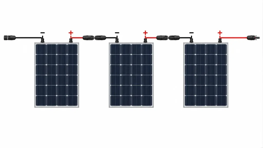
A series PV string is created by connecting the positive output of one module to the negative output of the next module.
The remaining positive lead at one end of the string and negative lead at the other become the string output.
Electrically:
Vmp,total ≈ Vmp1 + Vmp2 + Vmp3 + …
Voc,total ≈ Voc1 + Voc2 + Voc3 + …
For matched modules:
string current remains approximately the current of one module.
Example: Three Modules in Series
Assume three identical modules each have:
Vmp: 40 V
Voc: 48 V
Imp: 13 A
Isc: 13.8 A
The resulting string is approximately:
| Parameter | One module | Three in series |
|---|---|---|
| Vmp | 40 V | 120 V |
| Voc | 48 V | 144 V |
| Imp | 13 A | 13 A |
| Isc | 13.8 A | 13.8 A |
The useful lesson is:
Series wiring increases voltage much faster than it increases connector current requirements.
However, that does not mean any number of modules can simply be connected in series.
The resulting string voltage has to stay within the permitted limits of the inverter, MPPT, cable, connector and other DC components.
Series Current Does Not Always “Stay the Same”
The usual statement:
“Current stays the same in series.”
is useful only when the modules are properly matched.
A series string carries one current through the complete circuit.
If modules have substantially different current characteristics, the lower-current module can limit the operating current of the string.
Differences may come from:
- different module models
- different module ratings
- shading
- soiling
- degradation
- different orientations
- electrical faults
This is one reason modules within a string are normally selected and arranged according to the module and inverter manufacturer’s design requirements rather than connected together only because their connectors fit.
Cold Weather Can Raise Series String Voltage
String voltage should not be checked using the STC Voc value alone.
PV module open-circuit voltage generally rises as cell temperature falls.
For a long series string, this can make the maximum cold-weather Voc significantly higher than:
number of modules × nameplate Voc at STC
The module manufacturer’s temperature coefficient and the project minimum design temperature therefore need to be considered when checking maximum system voltage.
This matters because exceeding the maximum DC input voltage of an inverter or another component can cause equipment damage or a non-compliant installation.
In practical terms:
Series-string length is often limited by cold-weather Voc, not by the connector’s ability to physically connect another module.
How MC4 Connectors Are Used in Parallel
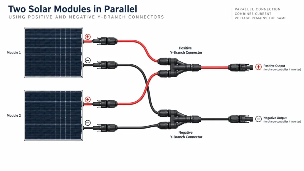
Parallel wiring connects positive conductors together and negative conductors together.
For matched PV strings:
voltage remains approximately the voltage of one string
while:
current from the parallel strings adds.
For two matched strings:
I_total ≈ I_string1 + I_string2
This is where branch connectors become particularly important.
A branch connector can combine two or more PV conductors into one output, but the connector and downstream cable must be suitable for the combined current.
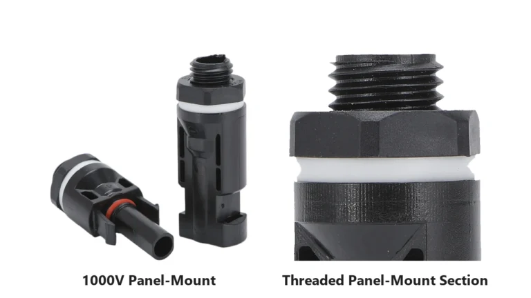
See MC4 Connector Types Explained for the difference between inline and branch connector configurations.
Example: Two Modules in Parallel
Using the same example module:
Vmp: 40 V
Voc: 48 V
Imp: 13 A
Isc: 13.8 A
Two matched modules connected in parallel provide approximately:
| Parameter | One module | Two in parallel |
|---|---|---|
| Vmp | 40 V | 40 V |
| Voc | 48 V | 48 V |
| Imp | 13 A | 26 A |
| Isc | 13.8 A | 27.6 A |
This is the opposite of series wiring:
Parallel wiring changes the current requirement much more than the voltage requirement.
That is why the combined output side of a PV branch connector needs particular attention.
A Branch Connector Must Be Sized for the Combined Side
This is one of the most important MC4 wiring checks.
Consider three parallel strings, each operating at approximately 13 A.
The combined operating current is approximately:
13 A + 13 A + 13 A = 39 A
A connector or cable that was suitable for one 13 A string is not automatically suitable for the 39 A combined output.
The following all need to be checked:
- branch connector rated current
- output cable cross-section
- cable ampacity
- cable outer diameter
- downstream connector rating
- terminal rating
- protection design
This is also why different UHCCY branch configurations should not automatically be assigned one generic current value.
For connector electrical ratings, see MC4 Connector Specifications.
Series-Parallel Wiring
Larger arrays often combine both methods.
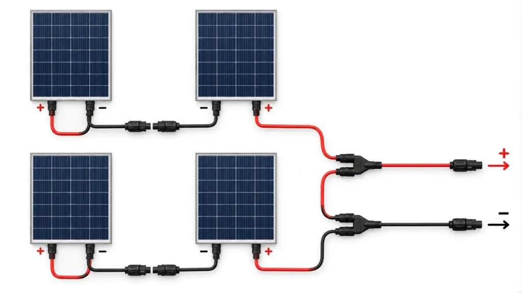
For example, four identical modules can be arranged as:
two modules in series per string
and then:
two strings connected in parallel
This is commonly described as:
2S2P
where:
2S = two modules in series
2P = two strings in parallel
Using the earlier 40 V / 13 A module example:
One 2-module series string provides approximately:
80 V Vmp
13 A Imp
Two identical strings in parallel provide approximately:
80 V Vmp
26 A Imp
This allows array voltage and current to be adjusted independently within the limits of the inverter or other power-conversion equipment.
The Parallel Strings Should Be Electrically Compatible
Physical connector compatibility is not enough when combining PV strings.
Parallel strings should be designed so their operating voltages are compatible.
Problems can arise when strings contain:
- different module models
- different numbers of modules in series
- substantially different Voc or Vmp
- incompatible orientations
- different electrical characteristics
A branch connector can physically join those wires, but it cannot correct a poor array design.
For many commercial PV systems, parallel combining is instead handled inside a properly designed combiner box where protection, monitoring and cable transitions can be managed more systematically.
MC4 Connector Polarity: Do Not Rely on Male vs Female Alone
One of the most persistent mistakes in online MC4 wiring guides is statements such as:
male connector = positive
or:
female connector = negative.
That is not a reliable universal wiring rule.
There are several reasons.
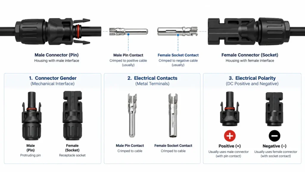
First, people may use “male” and “female” to describe either:
- the external plastic housing
- or the internal metal pin/socket contact
Those descriptions can point in opposite directions.
Second, the relationship seen on a PV module output is not automatically the same relationship seen on the equipment or extension-cable side of the mating connection.
For example, two connectors that mate with each other must necessarily have complementary interfaces while maintaining the same electrical polarity through the connection.
The practical rule is:
Polarity comes from electrical identification—not connector gender.
Use:
- markings
- module documentation
- equipment documentation
- cable identification
- appropriate electrical test equipment where required
Do not determine DC polarity from housing shape alone.
How to Verify PV Polarity
For new installations, polarity should be established from the module and equipment documentation before final connections are completed.
Where field verification is required, it should be performed with suitable test equipment by personnel competent to work on PV DC systems.
This matters because PV modules produce voltage whenever sufficient light is present.
Simply switching off an inverter does not necessarily remove voltage from every part of the array.
A polarity error can result in:
- equipment damage
- reverse-voltage conditions
- protection-device operation
- arcing during an incorrect connection
- commissioning failure
The safe design approach is therefore to identify and label polarity before mating the final circuit connections.
Does Parallel Wiring Always Require a Fuse?
No.
This is an area where many simplified solar wiring guides become misleading.
Parallel PV strings create the possibility that healthy strings can feed fault current back into a faulted string.
Whether overcurrent protection is required depends on factors including:
- available current from all sources
- conductor ampacity
- module maximum series fuse rating
- inverter backfeed characteristics
- number of parallel strings
- applicable electrical code
Under NEC 690.9, PV circuits can exist where an additional OCPD is not required when the conductors have sufficient ampacity and available currents remain within the specified limits.
Other configurations require protection because parallel sources can supply fault current exceeding the conductor or equipment rating.
So the useful rule is not:
“parallel = always add a fuse.”
It is:
Evaluate the available fault current and the protection requirements of the complete PV circuit.
For U.S. projects, refer to the applicable edition of NFPA 70 (NEC), particularly Article 690.
External reference:
NFPA — National Electrical Code
For international PV array design, IEC 62548-1 covers requirements including DC array wiring and electrical protection.
External reference:
IEC 62548-1 — Photovoltaic (PV) arrays — Part 1: Design requirements
Branch Connector or Combiner Box?
A branch connector and a combiner box can both combine parallel PV circuits, but they are not equivalent solutions.
Branch Connector
Most appropriate when:
- only a small number of conductors need combining
- the combined current remains within connector and cable limits
- required protection is handled elsewhere
- a compact in-line solution is suitable
Combiner Box
More appropriate when the project needs:
- multiple parallel strings
- string fuses
- surge protective devices
- disconnecting devices
- larger cable transition
- monitoring
- organized maintenance access
As array scale and fault-current complexity increase, a purpose-designed combiner enclosure generally provides more control than stacking additional branch adapters.
MC4 Extension Cables and Wiring
An extension cable does not change the fundamental series or parallel topology.
Its purpose is to extend the conductor between two connection points.
However, adding cable length introduces another design issue:
voltage drop.
Voltage drop depends mainly on:
- conductor resistance
- conductor cross-section
- cable length
- current
Parallel arrays can become especially sensitive because their combined current is higher.
This means a cable size suitable for one module lead may not be appropriate for a long combined-output run.
The cable also has to match the connector in two separate dimensions:
conductor cross-section
and
cable outer diameter.
These requirements are explained further in MC4 Connector Specifications.
Never Disconnect PV Connectors Under Load
A PV connector is normally a connection device, not a load-break switch.
Stäubli’s current MC4 installation instructions explicitly state that PV plug connections must not be disconnected under load.
External reference:
Stäubli — MC4 / PV Connector Assembly and Installation Resources
Opening a loaded DC connection can create an electrical arc.
DC arcs are particularly important because there is no natural current zero crossing every half-cycle as there is in AC power.
Before separating PV connectors, follow the equipment manufacturer’s shutdown procedure and applicable safe-working requirements.
The exact isolation method depends on the PV system architecture.
The Connector Must Also Be Mechanically Supported
Correct electrical wiring is not enough if the completed connector is left under mechanical stress.
Avoid installations that leave connectors:
- hanging from their own cable weight
- lying in standing water
- rubbing against moving structures
- under continuous tension
- sharply bent at the cable gland
- exposed to repetitive tracker movement without suitable support
Stäubli’s guidance for tracker systems specifically emphasizes mechanically isolating PV connector contacts from static and dynamic loads.
External reference:
Stäubli — PV DC Connections in Single-Axis Tracker Systems
The underlying principle applies more broadly:
The electrical contact should not be used as a structural support point for the cable.
Wiring and Crimping Are Two Different Tasks
This distinction is useful because the terms are often mixed.
Wiring determines:
- where the conductors connect
- circuit polarity
- series/parallel topology
- voltage
- current
- protection requirements
Crimping determines:
- how the conductor is mechanically and electrically terminated inside a field-assembled connector
A circuit can therefore have the correct wiring topology but still fail because of a poor termination.
Likewise, a perfect crimp does not correct reversed polarity or an incorrectly designed parallel circuit.
For field termination, see How to Crimp MC4 Connectors.
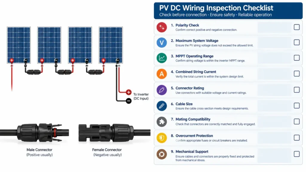
A Practical Pre-Connection Check
Before approving the final PV connector layout, verify the complete connection path.
| Check | Question |
|---|---|
| Module | Are the module electrical ratings known? |
| Series voltage | Is maximum cold-weather Voc below equipment limits? |
| MPPT range | Will operating Vmp remain inside the inverter’s usable range? |
| Parallel current | Has the combined current been calculated? |
| Connector | Is the exact connector rated for the voltage and current? |
| Cable | Are conductor size and cable OD suitable? |
| Polarity | Has + / − been verified independently of connector gender? |
| Mating system | Are the connectors approved/documented mating counterparts? |
| Protection | Has overcurrent protection been evaluated for the actual circuit? |
| Installation | Are connectors fully mated, sealed and mechanically supported? |
Key Takeaway
MC4 connector wiring should be understood as an electrical system problem rather than a plug-matching exercise.
The most important rules are:
- Series wiring adds voltage.
- Parallel wiring adds current.
- Cold-weather Voc can limit maximum series-string length.
- The combined side of a branch connector must carry the combined current.
- Male/female connector terminology does not independently define polarity.
- Parallel circuits require an overcurrent-protection assessment—not an automatic assumption.
- PV connectors should not be disconnected under load.
- Connector, cable, topology and protection must be selected as one system.
For connector configurations and electrical ratings, start from the Solar Connector category and verify the exact product required for the project.