Table of Contents
MC4 Connector Types Explained: Inline, Branch, Panel-Mount, Fuse & Diode
Search for “MC4 connector types” and you will quickly find several different classification systems.
Some guides compare MC4, MC3, H4 and other PV connector families. Others call male and female connectors, Y branches, fuse connectors and panel-mount connectors different MC4 types.
Both approaches answer a different question.
For practical connector selection, it is more useful to separate connector family, functional configuration, electrical rating, cable size and mating interface instead of treating all of them as “types.”
MC4 is a protected trademark of Stäubli, so UHCCY uses Solar Connector or PV Connector for its own products. This article uses “MC4 connector types” because it is the terminology commonly searched by people trying to understand this style of photovoltaic connection.
For a general introduction to MC4 terminology, ratings and compatibility, start with the MC4 Connector Guide.
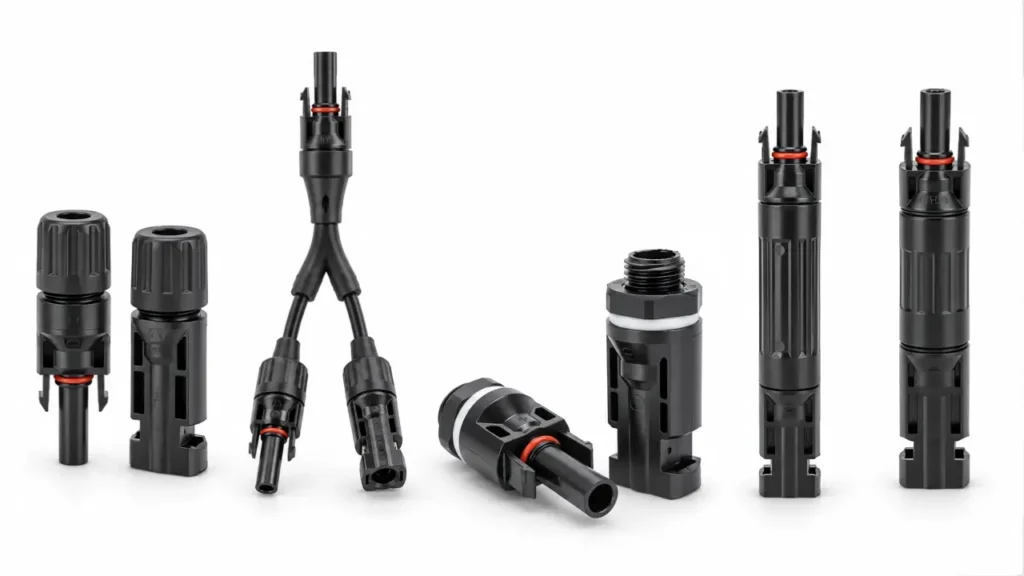
What Does “MC4 Connector Type” Actually Mean?
Before comparing individual designs, it helps to separate six different ways a PV connector can be classified.
| Classification | Examples | What it actually describes |
|---|---|---|
| Connector family | Original MC4, MC4-Evo 2, H4, MC3 | A manufacturer’s connector system or product family |
| Functional configuration | Inline, branch, panel-mount, fuse, diode | What the connector does in the PV circuit |
| Mating interface | Male / female | Which connector interface mates with the counterpart |
| Electrical rating | 1000 V, 1500 V, different current ratings | The approved electrical operating range |
| Cable configuration | 2.5, 4, 6 or 10 mm², different cable ODs | Which conductor and cable dimensions the contact and seal accept |
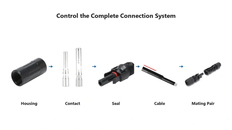
| Termination method | Crimp, spring clamp, factory pre-assembled | How the conductor is terminated inside the connector |
These categories should not be treated as interchangeable.
For example, a 1500 V connector is not automatically a separate connector function, just as a 6 mm² contact is not automatically a new connector family.
Likewise, “male” and “female” describe a mating relationship rather than the job the connector performs in the PV circuit.
This distinction makes connector selection much easier.
The Five Main Functional PV Connector Types
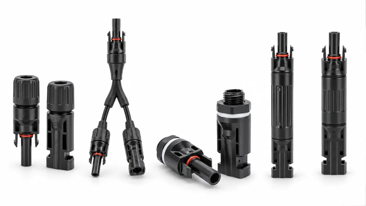
For the type of photovoltaic connection system UHCCY supplies, most applications can be grouped into five functional configurations.
| Functional type | Main purpose | Typical installation point | Main selection concern |
|---|---|---|---|
| Inline cable connector | Join two PV conductors | Module leads, string cables, extension cables | Cable size, current, voltage and mating family |
| Branch connector | Combine parallel conductors | Parallel strings or module groups | Combined current and number of branches |
| Panel-mount connector | Create a fixed feedthrough | Enclosures, equipment panels, junction boxes | Mounting structure and sealing |
| Inline fuse connector | Add fuse protection into a cable connection | PV string protection | Fuse rating and system protection design |
| Diode connector | Add an inline diode function | Application-specific DC circuits | Diode function, current and voltage |
The exact electrical ratings still depend on the specific connector model. IEC 62852 covers safety requirements and testing for DC connectors used in photovoltaic systems, but it does not mean every PV connector has the same voltage, current or cable range.
For detailed electrical parameters, see MC4 Connector Specifications.
1. Inline Cable Connectors
The standard inline cable connector is the most familiar PV connector configuration.
Its job is simple:
join one PV conductor to another PV conductor through a locking, insulated and environmentally protected connection.
It is commonly used between:
- PV modules
- module leads and extension cables
- string cables
- combiner-box leads
- inverter DC wiring
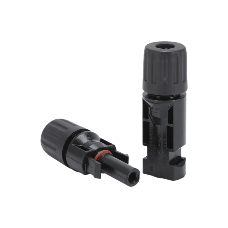
An inline pair normally consists of two complementary mating connectors, each terminated to a cable.
The important selection variables are not simply whether two housings look alike.
The connector, crimp contact, conductor cross-section, cable outside diameter, mating counterpart and applicable rating all need to belong to a compatible connection system.
UHCCY inline PV connector options are organized under the Solar Connector category rather than being marketed as Original MC4 products.
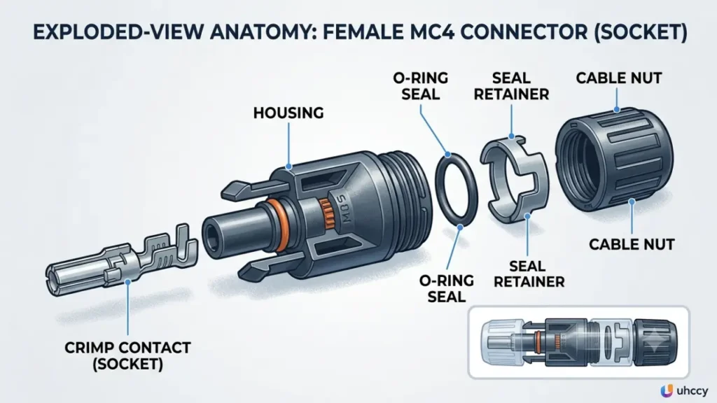
Male and Female Are Not Two Different Applications
Male and female connectors are frequently listed as two separate “MC4 connector types,” but this can be misleading.
They are two sides of a mating pair.
They normally perform the same electrical connection function.
Another source of confusion is that housing gender and metal contact gender are not always described in the same way. Depending on the manufacturer’s terminology, a housing that appears male externally can contain a socket contact, while the corresponding housing contains a pin contact.
For that reason:
do not use male/female terminology alone to determine PV polarity.
Positive and negative polarity should be verified from equipment markings, wiring documentation and appropriate electrical testing procedures.
The MC4 Connector Wiring Guide explains polarity, series and parallel connections in more detail.
2. Branch Connectors
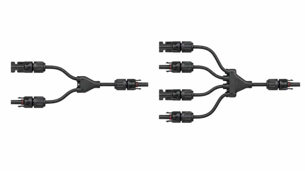
Branch connectors are used when PV conductors need to be combined or distributed, most commonly in parallel connections.
Common configurations include:
- 2-to-1
- 3-to-1
- 4-to-1
- other multi-branch arrangements
They may be sold in Y-shaped, T-shaped or other housing geometries.
The important point is that Y and T describe the mechanical arrangement of the housing more than the fundamental electrical purpose.
A 2-to-1 Y branch and a correctly designed 2-to-1 T branch can both perform the same basic job: combining two parallel conductors into one output.
Stäubli similarly describes its branch connector products as components for parallel or series-parallel PV connections.
The Combined Side Is the Critical Side
Branch connector selection becomes more important after multiple currents are combined.
As a simplified example:
if two PV branches each carry current into one combined output, the output-side connector and cable may need to carry approximately the sum of those branch currents.
That does not mean every installation can simply calculate two currents and select the next larger connector.
Module short-circuit current, continuous-current design rules, cable ampacity, connector ratings, protective devices and applicable electrical codes all need to be considered in the complete system design.
This is one reason UHCCY treats 2-to-1, 3-to-1 and 4-to-1 connectors as application configurations rather than assuming they can all use the same current specification.
3. Panel-Mount and Bulkhead PV Connectors
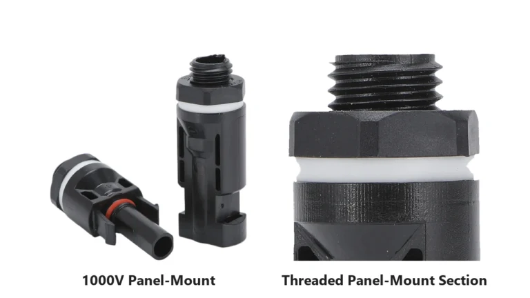
A panel-mount connector creates a fixed electrical connection point through an enclosure, equipment panel or similar structure.
Instead of both sides being free cable connectors, one side is mechanically mounted to the equipment.
Typical applications include:
- inverter housings
- PV junction boxes
- combiner boxes
- control enclosures
- DC equipment panels
Stäubli refers to this product category as panel receptacles within its Original MC4 portfolio.
Third-party products may also be described as:
panel-mount PV connectors
or
bulkhead solar connectors
depending on the mounting construction.
The main selection questions are different from those for an ordinary cable-to-cable connector.
A panel-mount design needs to account for:
- panel opening or thread dimensions
- mounting method
- enclosure wall thickness where applicable
- sealing arrangement
- internal electrical termination
- external mating connector
- voltage and current rating
This is why a panel-mount connector should not simply be selected because its external mating face looks like the connector already used on the cable.
4. Inline Fuse Connectors
An inline fuse connector combines a PV connector interface with a fuse holder or integrated fuse assembly.
Its purpose is to introduce overcurrent protection directly into a PV cable path without using a separate external fuse holder at that exact connection point.
Stäubli includes in-line fuses as a separate functional component within its PV connection portfolio.
This type becomes particularly relevant when string-level protection is required by the electrical design.
However, an inline fuse connector should not be selected by connector shape alone.
The designer or buyer needs to verify at least:
- system voltage
- required fuse rating
- fuse type and breaking capacity
- connector current capability
- cable size
- environmental rating
- applicable protection requirements
A fuse connector is therefore both a connection component and a protection component.
The fuse rating should come from the PV system design, not from whichever fuse happens to fit inside the housing.
5. Diode Connectors
Diode connectors are less common than standard inline, branch or fuse connectors, but they serve a distinct electrical function.
A PV diode connector places a diode in the cable path to control current direction for a specific circuit design.
This is not the same thing as the bypass diodes inside a PV module junction box.
The two devices solve different problems.
A module bypass diode is normally connected across a section of PV cells so current can bypass that section under certain shading or fault conditions.
An inline diode connector is installed in the external DC wiring path and needs to be selected for the intended circuit function.
For this reason, the important specifications include:
- permitted forward current
- reverse-voltage capability
- voltage drop and resulting power loss
- heat dissipation
- cable and connector ratings
- installation environment
“MC4 diode connector” is a common search phrase, but UHCCY refers to third-party versions as PV Diode Connectors or Solar Diode Connectors unless a product is genuinely part of the Stäubli MC4 system.
What About Y Connectors vs T Connectors?
Y and T connectors are often presented online as completely different MC4 connector types.
For selection purposes, it is more useful to ask:
What circuit topology does the connector create?
A Y-shaped 2-to-1 branch and a T-shaped 2-to-1 branch may both provide a parallel combining function.
Their physical designs can still differ in:
- housing size
- cable routing
- installation clearance
- contact construction
- sealing
- rated current
- number of branches
So the choice should not be reduced to:
Y is better than T
or
T is better than Y.
Choose the branch connector according to its documented electrical rating, mechanical design and installation layout.
The housing shape comes after those requirements.
Is an Extension Cable Another MC4 Connector Type?
Not exactly.
An extension cable is better understood as a cable assembly.
It typically consists of:
PV cable + connector at one end + connector at the other end
The connectors themselves still belong to one of the connection systems discussed above.
This distinction matters for procurement because a finished extension cable introduces additional variables:
- conductor size
- cable construction
- cable length
- voltage drop
- connector termination quality
- polarity
- connector mating family
A properly assembled extension cable is therefore more than “two MC4 connectors with wire between them.”
What About MC4, MC4-Evo 2, H4, T4 and MC3?
These belong to a different classification dimension.
They refer to connector families, generations or manufacturer-specific systems rather than five different electrical jobs.
The Original MC4 and MC4-Evo products, for example, are part of Stäubli’s product portfolio. Stäubli explicitly identifies MC4 as its protected trademark.
Other manufacturers have their own PV connector systems.
Similar appearance does not make those systems the same product.
This distinction becomes especially important when two connectors from different manufacturers physically fit together.
Mechanical fit is not proof of approved intermatability.
That subject deserves separate treatment because compatibility involves product documentation, certification and project requirements rather than appearance alone.
How to Choose the Correct PV Connector Type
Instead of starting with the connector shape, use the electrical function as the first decision.
Step 1: Define the Function
Ask what the connection needs to do:
Join one cable to another?
Use an inline connector configuration.
Combine parallel branches?
Evaluate a branch connector.
Pass through an enclosure?
Evaluate a panel-mount connector.
Add string-level fuse protection?
Evaluate an inline fuse connector.
Introduce an inline diode function?
Evaluate a diode connector.
Step 2: Confirm System Voltage
The exact connector model must be rated for the intended DC system voltage.
A similar-looking 1000 V connector and 1500 V connector should not be assumed to be interchangeable.
Step 3: Calculate the Current at That Location
This is particularly important for branch connectors.
The current carried by the combined output may be significantly higher than the current on each individual branch.
Step 4: Match the Cable
Verify both:
conductor cross-section
and
cable outside diameter.
Conductor cross-section affects the electrical contact.
Cable outside diameter affects sealing and strain relief.
Step 5: Verify the Mating System
Do not select a connector only because it physically inserts into the existing connector.
Confirm the intended mating counterpart and available intermatability documentation.
Step 6: Verify the Installation Method
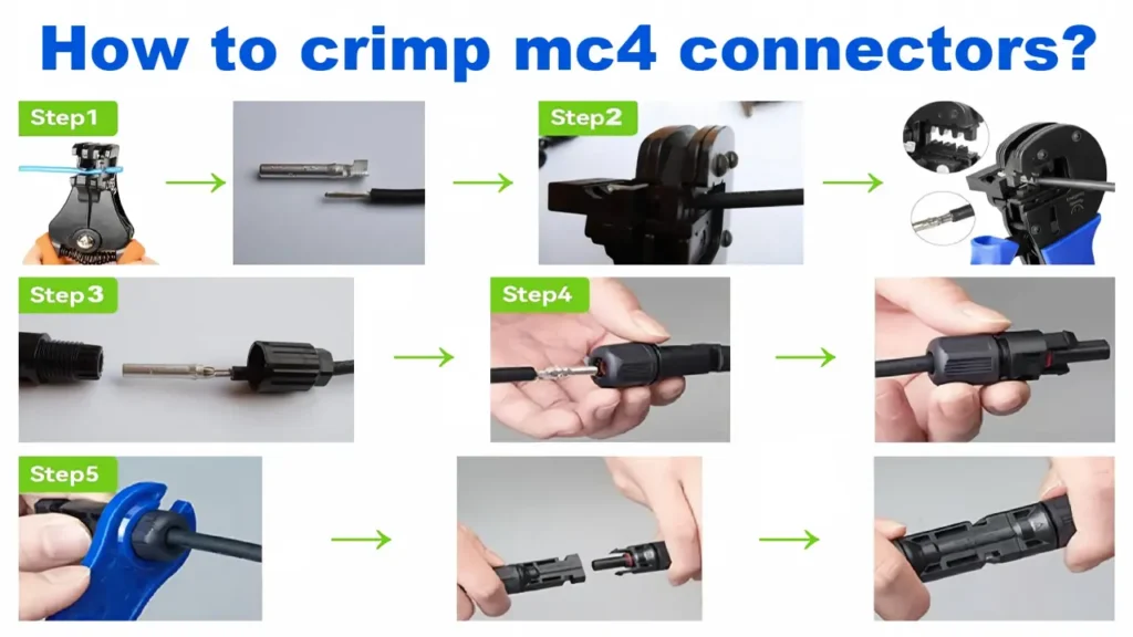
Field-crimp connectors need the correct contact, stripping dimensions and crimp tooling.
See How to Crimp MC4 Connectors for the complete field-termination process.
A Better Way to Specify Connectors for Purchasing
For procurement, “MC4 type” is not a complete specification.
A purchasing description should identify the actual requirements.
For example:
Function: 2-to-1 PV branch connector
System voltage: required project voltage class
Combined current: required output current
Cable: conductor cross-section and outer diameter
Mating interface: exact approved mating counterpart
Environmental requirement: applicable installation conditions
Compliance: certificate or test documentation required for the project
This prevents one of the most common sourcing problems:
two suppliers quoting products that look similar but are not technically equivalent.
For UHCCY products, use the Solar Connector category as the starting point and then compare the exact model specifications required by the project.
Key Takeaway
There is no single useful answer to “how many MC4 connector types are there?” until type is defined.
For PV system design and purchasing, the clearest functional classification is:
inline connector → branch connector → panel-mount connector → fuse connector → diode connector.
Male and female describe the mating interface.
1000 V and 1500 V describe electrical ratings.
2.5, 4, 6 or 10 mm² describe cable/contact configurations.
MC4, MC4-Evo 2, H4 and other names describe connector families or manufacturer-specific systems.
Keeping those dimensions separate makes connector selection more accurate and makes it much easier to compare products from different suppliers.
Frequently Asked Questions
What are the main MC4 connector types?
When classified by function, the main PV connector configurations are inline cable connectors, branch connectors, panel-mount connectors, inline fuse connectors and diode connectors.
Are male and female MC4 connectors different types?
They are complementary mating interfaces rather than different electrical applications. They normally work together as a connector pair. Male/female terminology should also not be used alone to determine positive and negative polarity.
What is the difference between an MC4 Y connector and a T connector?
Both can be designed as branch connectors for parallel PV wiring. The main difference is usually the physical housing and cable-routing geometry. Always compare the exact electrical rating and construction rather than choosing only by Y or T shape.
What is an MC4 branch connector used for?
A branch connector combines or distributes PV conductors, most commonly when modules or strings are connected in parallel. The combined side may carry more current than each individual branch, so current rating and cable sizing need to be checked carefully.
Is a 1500 V MC4 connector a different connector type?
Voltage rating is better treated as an electrical specification rather than a functional connector type. Two connectors may perform the same inline connection function while being designed for different voltage classes.
Is an MC4 fuse connector the same as a normal MC4 connector?
No. An inline fuse connector combines a PV connection interface with a fuse function. Fuse selection must be based on the protection requirements of the PV circuit.
Is a diode connector the same as a solar-panel bypass diode?
No. An inline PV diode connector is installed in the external cable path. A bypass diode is normally installed inside the module junction box across groups of solar cells.
Can different MC4-looking connector types be mixed?
Do not assume compatibility from appearance or physical fit. Verify the exact connector systems, manufacturer documentation and applicable certification or installation requirements before mating different products.