Table of Contents
A PV connector can look perfectly assembled from the outside and still contain a poor electrical termination inside.
That is why learning how to crimp MC4 connectors is not simply about squeezing a metal contact around a cable.
A reliable field-assembled PV connection depends on three separate fits:
conductor → crimp contact
contact → connector housing
cable jacket → gland and seal
The crimping tool controls only the first of these. All three must be correct for the finished connection to perform as intended.
UHCCY uses Solar Connector or PV Connector for its own products. The procedure below therefore explains the principles of crimp-type PV connector assembly rather than assigning one universal strip length, torque or die specification to every connector on the market.
For connector terminology and compatibility, start with the MC4 Connector Guide.
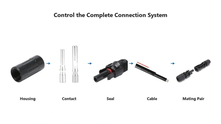
Before Crimping: Match the Complete Connection System
The most important step happens before the crimping tool is used.
Do not start with:
“I have a 4 mm² cable, so I need the 4 mm² slot on the crimper.”
Start by verifying the complete combination.
| Item | What needs to match |
|---|---|
| PV cable conductor | Contact conductor range |
| Cable outer diameter | Connector seal and gland range |
| Metal contact | Exact connector housing |
| Crimp die | Exact contact and conductor |
| Connector housing | Intended mating counterpart |
| Voltage/current rating | Actual PV circuit |
| Assembly method | Manufacturer’s instructions |
A cable can have the correct conductor cross-section but the wrong outer diameter.
A contact can fit into a crimping die but belong to another connector family.
Two connector housings can physically mate while not being an approved mating combination.
Crimping does not correct any of these mismatches.
For conductor size, cable OD and electrical ratings, see MC4 Connector Specifications.
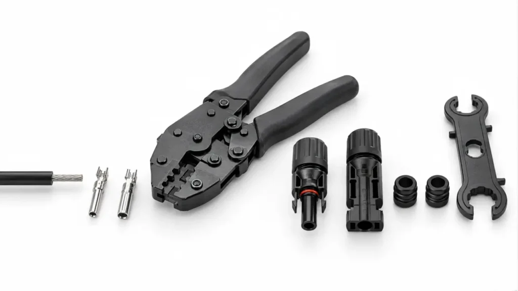
Tools Needed for PV Connector Crimping
A typical field-crimp installation requires four basic tool functions.
| Tool | Purpose |
|---|---|
| Cable cutter | Creates a clean perpendicular cable end |
| Wire stripper | Removes insulation without damaging conductor strands |
| Crimping tool and die | Forms the conductor-to-contact termination |
| Assembly wrench / torque tool | Completes the cable gland and housing assembly |
Depending on the connector manufacturer, additional gauges, test plugs or special assembly tools may be specified.
UHCCY connector installation tools are available in the Solar Connector Tools range.
Why the Crimping Die Matters
A ratchet mechanism is useful because it helps complete a consistent crimping stroke, but ratchet does not automatically mean correct.
The critical part is whether the tool and die geometry are suitable for:
the exact contact + conductor combination.
A generic crimper may have cavities marked:
2.5 mm²
4 mm²
6 mm²
but those markings alone do not prove that its crimp geometry is correct for every PV contact sold for those conductor sizes.
Where certification or project compliance matters, use the tooling specified or approved for the exact connector system.
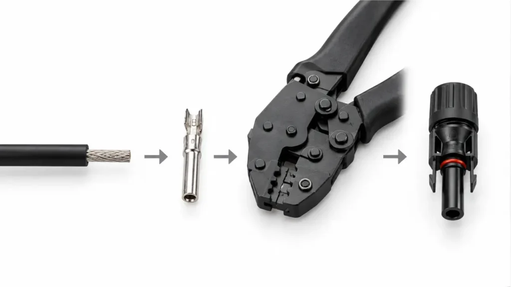
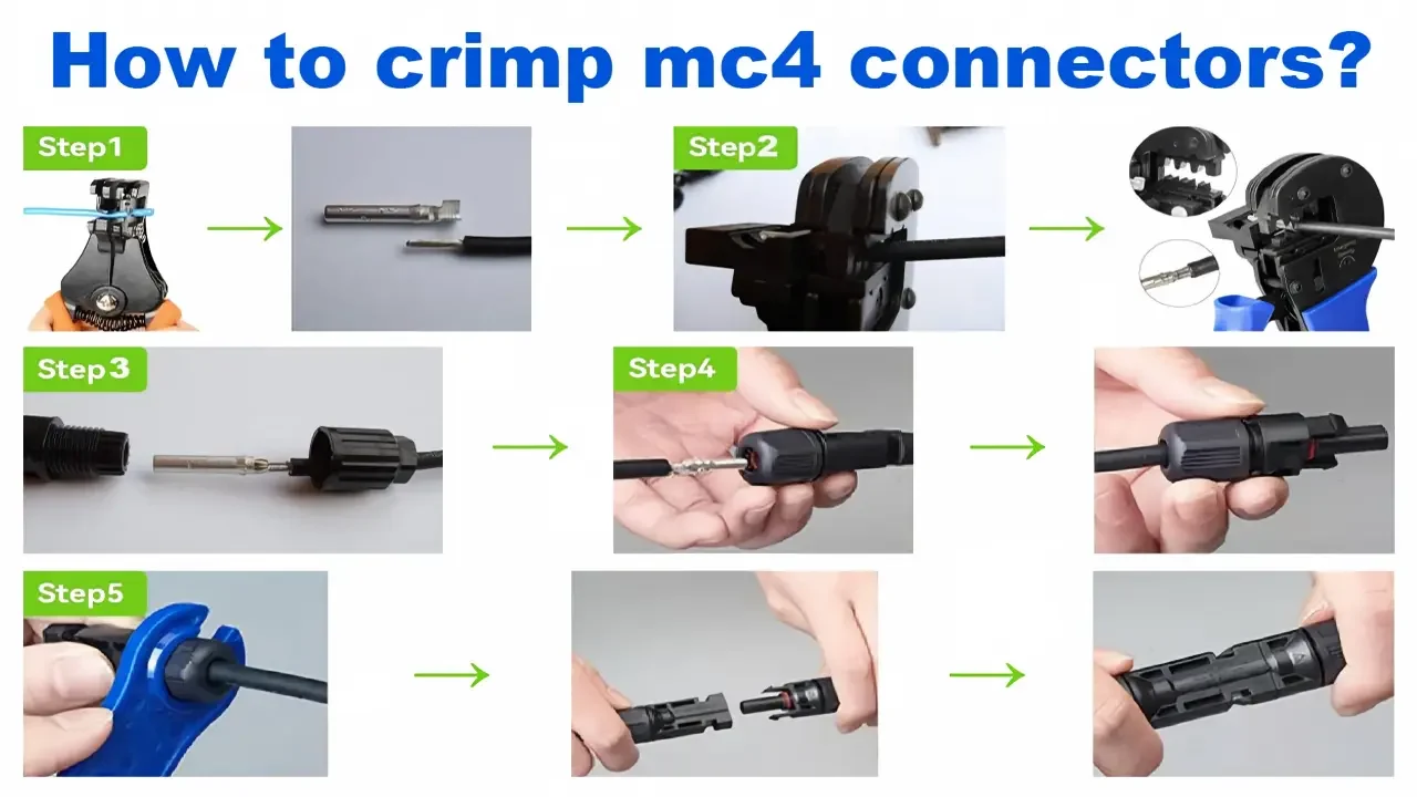
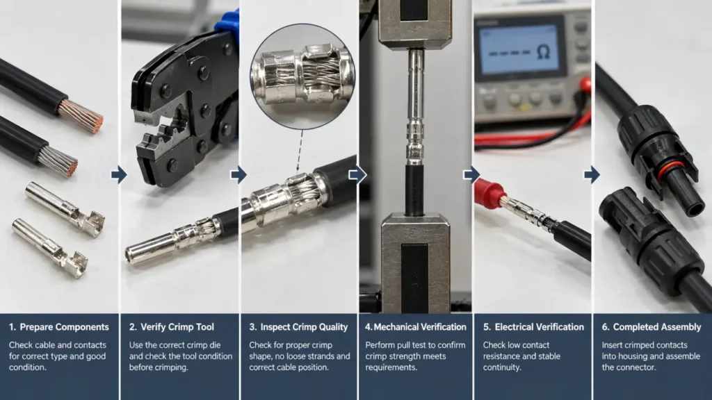
How to Crimp MC4 Connectors?
Step 1: Cut the PV Cable Cleanly
Cut the cable square to the conductor.
A crushed or strongly angled cable end makes the next stripping and insertion steps less consistent.
Before cutting, also confirm that enough cable length remains for:
- routing
- bend radius
- connector support
- final equipment termination
Avoid designing the cable so tightly that the completed connector becomes a mechanical tension point.
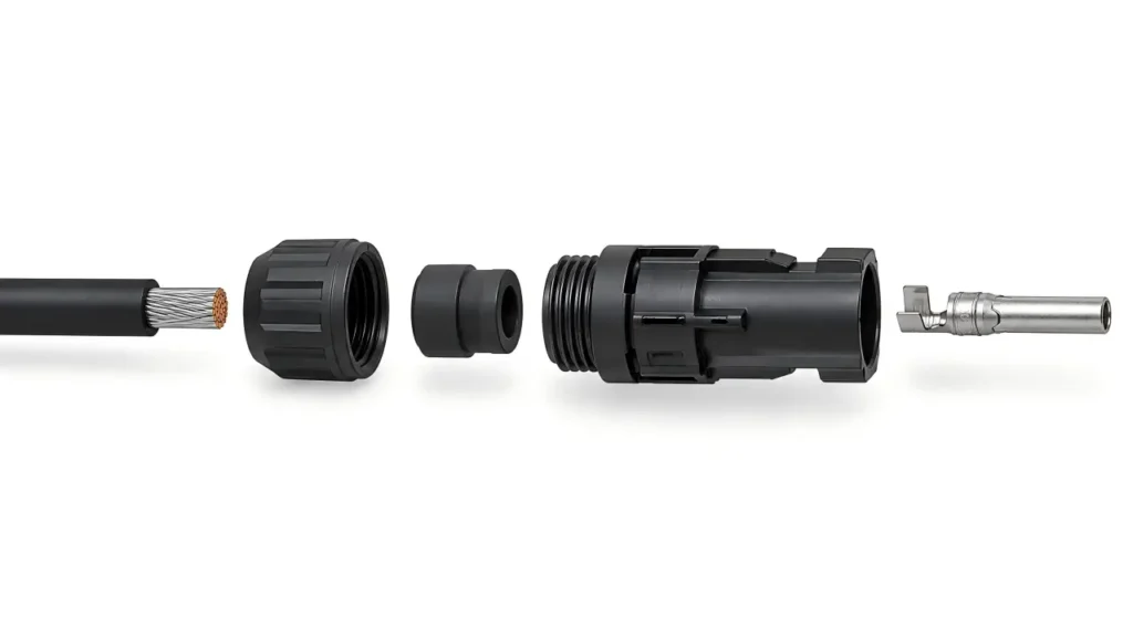
Step 2: Install the Gland Components Before Crimping
For connector designs where the cable gland, sealing component or back nut must slide over the cable before the contact is installed, do this now.
This is a simple step, but forgetting it can mean cutting off a correctly crimped contact and starting again.
The exact component order depends on the connector design, so follow the assembly drawing for the product being installed.
Step 3: Strip the Cable to the Exact Product Requirement
This is where many online crimping guides become misleading.
There is no single universal MC4 strip length that should be copied across every PV connector.
Different contact designs require different conductor exposure.
Use the strip length specified for the exact contact and connector.
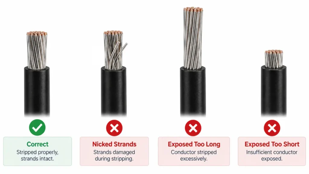
A correct strip should expose enough conductor to fill the intended crimp area without leaving unnecessary bare copper outside the termination.
During stripping:
do not cut conductor strands
and
do not scrape or deeply score the remaining strands.
Reducing the conductor cross-section at the termination can change both mechanical retention and electrical performance.
Why “About 7 mm” Is Not Good Enough for Procurement
A field technician working on one documented connector may know the specified stripping tolerance.
A purchasing specification covering several connector platforms should not simply say:
Strip approximately 7 mm.
Instead, the installation instruction for each connector model should define the stripping requirement.
That prevents an assembly value belonging to one contact from being reused on another.
Step 4: Insert the Conductor Fully Into the Contact
Insert all conductor strands into the crimp barrel.
No strands should remain folded backward or outside the intended conductor-crimp area.
At the same time, avoid pushing the cable so far forward that insulation enters a conductor-crimp zone that is intended only for metal strands.
The exact correct position depends on the contact construction.
Some contacts provide an inspection area where conductor position can be checked visually.
The general goal is straightforward:
All intended conductor strands should be captured by the contact in the position defined by its design.
Do not twist, trim or remove strands simply to force a conductor into an undersized contact.
If it does not fit correctly, verify the cable/contact combination.
Step 5: Position the Contact in the Correct Crimp Die
Place the contact in the die cavity specified for the conductor and contact.
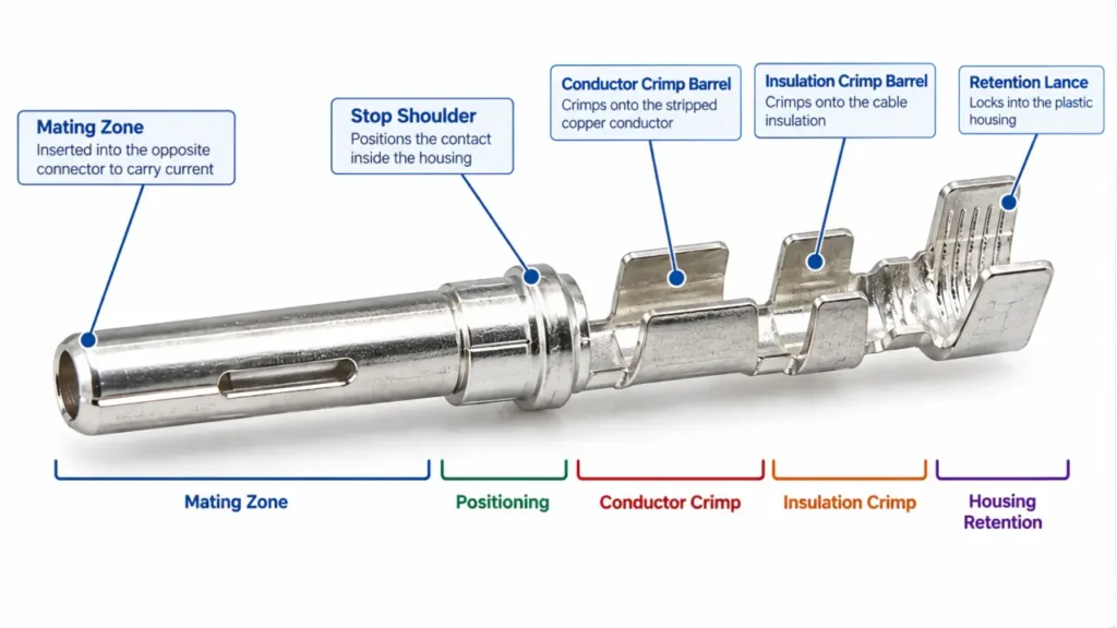
The contact should be positioned so that the tool compresses the intended crimp barrel—not the mating surface, retention feature or locking section of the contact.
This matters because a metal contact normally performs several different jobs:
front section: mating electrical interface
middle/rear section: conductor termination
retention feature: locks the contact inside the housing
Damaging the mating or retention section while crimping can create a connector that looks assembled but cannot mate or lock correctly.
Step 6: Complete the Full Crimping Stroke
Once the conductor and contact are correctly positioned, complete the crimping cycle according to the tool instructions.
With a ratcheting crimper, the mechanism normally helps prevent premature release before the cycle is complete.
Do not:
- partially crimp and reposition the contact
- crimp the same area repeatedly to “make it tighter”
- crush the contact with pliers after crimping
- flatten a contact that looks different from another brand
- add solder simply because the crimp appears loose
If the crimp looks incorrect, identify the cause.
Common causes include:
wrong die
wrong contact
wrong conductor size
incorrect tool position
damaged tooling
incomplete conductor insertion
A questionable termination is better remade than manually reshaped.
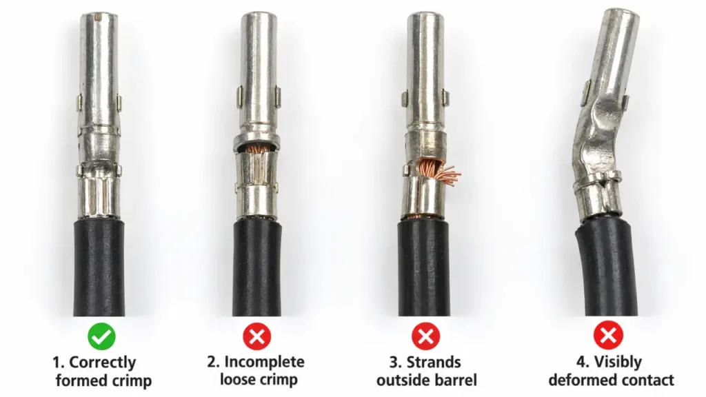
What Should a Good PV Connector Crimp Look Like?
A visual inspection cannot prove every aspect of electrical performance, but it can identify many obvious assembly defects.
| Check | Acceptable condition | Warning sign |
|---|---|---|
| Conductor strands | All intended strands captured | Strands outside or cut away |
| Cable insulation | Stops in the intended location | Insulation trapped in conductor crimp |
| Contact body | Straight and undamaged | Bent or crushed mating section |
| Crimp formation | Consistent with specified tool geometry | Uneven, open or visibly distorted |
| Retention feature | Undamaged | Bent locking lance / retention section |
| Exposed copper | Only as permitted by design | Long bare section outside contact |
| Cable/contact match | Conductor fits contact correctly | Conductor forced into undersized barrel |
Do not use another brand’s finished crimp appearance as the sole acceptance standard.
Different contact designs can produce different crimp profiles.
The correct reference is the assembly specification for the exact connector.
Step 7: Perform a Mechanical Crimp Check
After crimping, confirm that the conductor is mechanically retained in the contact.
For normal field assembly, a controlled manual retention check can reveal an obviously loose termination.
However:
a hand pull is not the same as a quantified pull-out test.
Do not publish or use a universal pull-force value for all PV connectors.
Formal pull-out requirements depend on:
- conductor cross-section
- contact design
- connector specification
- applicable test method
For production qualification or supplier approval, use the documented acceptance criteria for the exact contact/cable combination.
Step 8: Insert the Contact Into the Housing
After the crimp has passed inspection, insert the contact into the correct connector housing.
Push it until the retention feature engages.
A properly seated contact should not simply slide back out when the cable is lightly pulled.
Do not force a contact that refuses to seat.
Possible causes include:
- wrong contact
- wrong housing
- contact installed in the wrong orientation
- damaged retention feature
- deformed contact from crimping
Forcing the assembly can damage the housing and make later inspection more difficult.
Step 9: Assemble the Cable Seal and Gland
Once the contact is locked inside the housing, complete the cable-entry sealing system.
The gland does two important jobs:
environmental sealing
and
mechanical strain relief.
This is why cable outer diameter matters even when conductor cross-section is correct.
A 4 mm² cable with an OD outside the connector’s permitted sealing range may crimp correctly but still produce an unsuitable finished connection.
Do not guess a universal tightening torque.
Use the value or assembly method defined for the exact connector.
For the Original MC4 system, Stäubli publishes product-specific assembly instructions rather than one universal installation value for every connector family.
Step 10: Complete the Final Assembly Check
Before the connector is placed into service, check the complete assembly rather than only the crimp.
| Final check | What to verify |
|---|---|
| Cable | Correct conductor size and OD |
| Crimp | No damaged strands or contact deformation |
| Contact retention | Contact fully locked in housing |
| Gland | Correctly assembled and tightened |
| Polarity | Verified independently of connector gender |
| Mating system | Correct mating counterpart |
| Housing | No cracks or damaged locking features |
| Cable support | Connector not carrying cable tension |
If the connection is part of new PV wiring, polarity should also be verified before final mating or commissioning.
See the MC4 Connector Wiring Guide for polarity, series and parallel wiring.
Five Crimping Mistakes That Matter Most
1. Using the Cable Size as the Only Selection Criterion
“4 mm² connector” is incomplete information.
The contact, housing and sealing range still need to match.
2. Damaging Strands During Stripping
A connector cannot restore copper that has been cut away.
Damaged strands reduce the effective conductor at exactly the location where electrical and mechanical integrity matter most.
3. Using the Wrong Die Because It Fits
A cable may physically fit into a die cavity without that die being correct for the contact geometry.
4. Crimping the Contact Correctly but Sealing the Wrong Cable OD
This creates a good conductor termination inside an incorrectly sealed connector.
5. Treating the Crimp as the Final Quality Check
The contact still has to seat, lock, seal and mate correctly.
This is why connector assembly should be evaluated as a complete process.
Should You Solder an MC4 Crimp Contact?
Do not add solder to a contact designed and documented for crimp termination unless the connector manufacturer’s instructions explicitly permit it.
Adding solder changes the termination from the tested assembly method and can change:
- conductor flexibility
- strain distribution
- thermal behavior
- insertion geometry
- serviceability
If a crimp is loose enough that solder appears necessary to rescue it, the better solution is normally to identify the incorrect cable/contact/tool combination and remake the termination.
Can You Crimp MC4 Connectors With Ordinary Pliers?
Ordinary pliers can deform a metal contact.
That is not the same as producing a controlled crimp geometry.
A proper crimp tool is designed to position and compress the contact in a repeatable way.
For professional installation, use the tool and die intended for the connector/contact combination.
If field installation is a regular part of your work, the Solar Connector Tools category includes crimping tools, wire strippers, cable cutters, assembly wrenches and related PV connector installation tools.
Field Installation and Production QC Are Different
A field installer needs a repeatable method for making one correct connection.
A manufacturer, cable-assembly supplier or procurement team has a different question:
How do we verify that the termination process remains consistent across production?
That requires more than tugging one finished cable.
A useful production or supplier-qualification plan can include:
| QC method | What it checks |
|---|---|
| Tool / die identification | Correct tooling is being used |
| Tool condition / calibration control | Process consistency |
| Visual crimp inspection | Strand capture and contact deformation |
| Crimp dimensions where specified | Repeatability against product specification |
| Pull-out testing | Mechanical retention |
| Electrical resistance / voltage-drop testing where specified | Electrical termination quality |
| Contact retention check | Correct housing assembly |
| Cable gland inspection | Sealing and strain relief |
| Lot traceability | Ability to investigate later failures |
Not every production line performs every test on every connector.
The correct inspection plan depends on the connector specification, production volume, customer requirements and applicable certification.
For a B2B buyer, the important question is not:
“Does your factory own a crimping machine?”
A better question is:
“How do you control the cable/contact/tool combination and verify crimp consistency?”
That answer tells you much more about the production process.
Why One Universal Crimping Number Is a Warning Sign
When comparing installation guides, be cautious if an article claims that all MC4 connectors require exactly:
one strip length
one torque
one die
one pull force
one contact-resistance limit
without naming the exact product.
MC4 refers to a specific Stäubli connector family, while many visually similar third-party PV connectors use different contacts, seals and assembly requirements.
Stäubli itself provides model-specific assembly instructions covering cable preparation, stripping, crimping, assembly inspection and gland installation for the Original MC4 family.
That is the correct model for technical documentation:
specific connector → specific cable/contact combination → specific assembly instruction
not:
black PV connector → generic internet number
A Better Crimping Standard for Buyers
If you purchase finished PV cable assemblies or field-assembly connector kits, specify more than the connector name.
A useful purchasing requirement should identify:
connector model
mating counterpart
contact
conductor cross-section
cable outside diameter
approved crimping method
required documentation
inspection requirements
This turns the crimp from a hidden manual operation into a controlled part of the product specification.
For UHCCY connector platforms, begin with the Solar Connector category and confirm the cable/contact configuration of the selected model.
Key Takeaway
Learning how to crimp MC4 connectors correctly is not about memorizing one strip length or squeezing a terminal as tightly as possible.
A reliable PV connector assembly depends on four things being matched:
cable
contact
tool
connector housing
Then the finished assembly still needs to be correctly seated, sealed, mated and supported.
The most important rules are therefore:
Use the exact contact intended for the cable and housing.
Use the specified tool and die rather than whichever cavity physically fits.
Do not damage conductor strands during stripping.
Inspect the contact before inserting it into the housing.
Verify contact retention after insertion.
Match cable OD to the gland and seal.
Do not rescue a poor crimp with solder or extra squeezing.
For production purchasing, control and verify the process—not just the finished appearance.