Table of Contents
MC4 Connector Specifications: Voltage, Current, Wire Size & IP Ratings
Search for MC4 connector specifications and you will find datasheets listing very different current ratings, voltage ratings, cable sizes, temperature ranges and IP ratings.
One source may describe an MC4 connector as 30 A and 1000 V DC. Another may list more than 50 A or a 1500 V rating.
That does not automatically mean one of them is wrong.
The more important question is:
Which exact connector, cable size, test standard and installation condition does the rating apply to?
MC4 is a protected Stäubli trademark. UHCCY uses Solar Connector or PV Connector for its own products. If you first need an explanation of MC4 terminology and compatibility, see the MC4 Connector Guide.
This guide explains how to read photovoltaic connector specifications correctly rather than treating “MC4” as one universal electrical rating.
There Is No Single Universal MC4 Connector Specifications
One of the most common specification mistakes is creating a table such as:
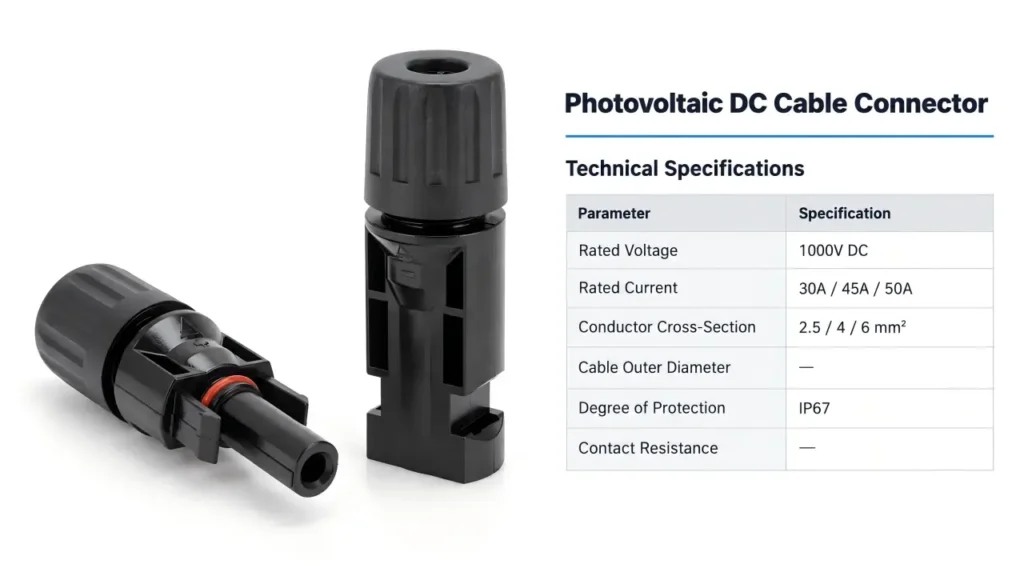
MC4 = 30 A / 1000 V / IP67 / 4–6 mm²
and assuming it applies to every connector with a similar shape.
It does not.
Even within one manufacturer’s connector family, electrical ratings may change according to conductor size, product generation and certification basis.
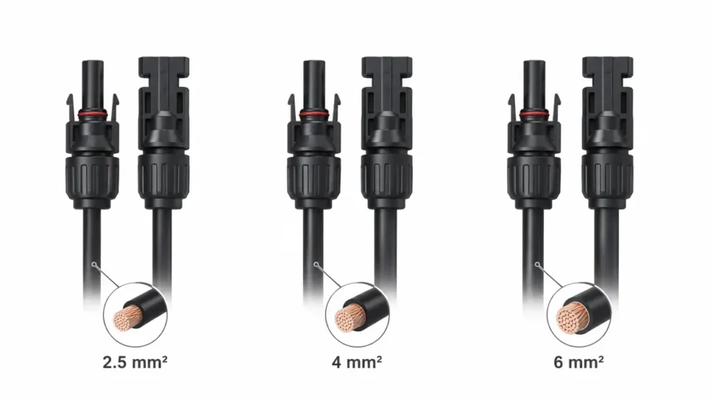
For example, current Stäubli MC4-Evo 2 documentation lists different IEC rated currents for 2.5, 4, 6 and 10 mm² conductors. The same product family also has separate UL current ratings expressed in AWG sizes.
That demonstrates the first rule for reading PV connector specifications:
A rating without its conditions is incomplete information.
The most important specifications normally include:
| Specification | What it tells you | What must also be checked |
|---|---|---|
| Rated voltage | Maximum intended system voltage under the stated approval | Exact connector model and certification |
| Rated current | Current the connection is rated to carry | Conductor size, standard and operating conditions |
| Conductor cross-section | Wire conductor size accepted by the contact | Correct crimp contact |
| Cable outer diameter | Jacket diameter accepted by the gland and seal | Actual PV cable OD |
| Contact resistance | Electrical resistance through the connection | Test method and condition |
| IP rating | Protection against ingress | Mated/unmated state and test conditions |
| Temperature range | Environmental operating range | Current loading and upper limiting temperature |
| Contact material | Conductive interface construction | Plating and connector design |
| Insulation material | Connector housing material | Exact product rather than generic assumptions |
| Applicable standard | Test and safety framework | Exact certificate and product coverage |
For UHCCY connector options, use the Solar Connector category and then verify the specifications of the exact model required for the project.
MC4 Connector Current Rating: Why 30 A Is Not a Universal Answer
A common search is:
How many amps can an MC4 connector handle?
There is no single correct current value for every MC4 or similar PV connector.
The current rating is linked to the complete conductive path:
cable conductor → crimp contact → connector interface → mating contact → cable conductor
A larger conductor does not automatically make every connector capable of carrying more current, but connector families may be designed and certified for different currents with different conductor sizes.
A Real Manufacturer Example
Current Stäubli MC4-Evo 2 technical documentation gives the following IEC values:
| Conductor cross-section | IEC rated current |
|---|---|
| 2.5 mm² | 39 A |
| 4 mm² | 45 A |
| 6 mm² | 53 A |
| 10 mm² | 69 A |
The same documentation gives different UL ratings when conductor sizes are expressed as AWG.
These are Stäubli MC4-Evo 2 ratings, not generic specifications that should be copied onto another manufacturer’s connector.
That difference is important.
If another supplier states:
30 A with 2.5 mm²
45 A with 4 mm²
50 A with 6 mm²
those values need to be supported by that connector’s own design, test data and certification—not by an MC4-Evo 2 datasheet.
Rated Current Is Not the Same as System Design Current
A connector’s rated current is also not automatically the current that should be used as the design limit for every PV system.
PV circuit design may need to consider:
- module short-circuit current
- parallel-string current
- conductor ampacity
- ambient temperature
- installation method
- protective-device sizing
- applicable electrical codes
The connector rating is one part of that system.
This becomes particularly important with branch connectors because current on the combined side can be higher than on each individual branch.
See MC4 Connector Types Explained for the difference between inline and branch configurations.
MC4 Connector Voltage Rating: 1000 V vs 1500 V
1000 V DC and 1500 V DC are both common voltage classes in photovoltaic systems.
However, the words “MC4 connector” alone do not tell you which voltage rating applies.
IEC 62852 covers connectors for DC photovoltaic applications with rated voltages up to 1500 V DC, but this does not mean every connector tested to an applicable PV connector standard automatically has a 1500 V rating. The exact product still needs its own declared and certified rating.
The official standard can be referenced here:
IEC 62852 — Connectors for DC application in photovoltaic systems
Why Voltage Rating Is More Than a Printed Number
Higher system voltage affects requirements such as:
- insulation design
- creepage and clearance
- material performance
- connector geometry
- test voltage
- pollution conditions
- mating-system design
For that reason, do not assume that two housings that look almost identical have the same voltage rating.
A 1500 V marking should belong to the exact connector model and configuration being purchased.
For UHCCY products, 1000 V and 1500 V variants should therefore be selected from their own model specifications rather than inferred from appearance.
Cable Cross-Section and Cable Outer Diameter Are Two Different Specifications
This is one of the most useful distinctions for purchasing PV connectors.
A connector datasheet may list both:
Conductor cross-section: 4 mm²
and
Cable outer diameter: 5.5–7.5 mm
These values describe different things.
Conductor Cross-Section
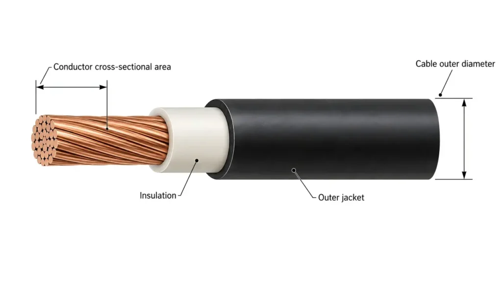
Cross-section refers to the conductive metal inside the cable.
Typical PV conductor sizes include:
2.5 mm²
4 mm²
6 mm²
10 mm²
The conductor size needs to match the crimp contact or other termination system.
Cable Outer Diameter
Outer diameter refers to the complete insulated cable jacket.
It determines whether the connector gland and sealing component can properly grip and seal the cable.
Two PV cables can both contain a 4 mm² conductor while having different outside diameters because their insulation and jacket constructions are different.
This means:
4 mm² compatible does not automatically mean every 4 mm² PV cable will seal correctly.
Both values must be checked.
MC4 Wire Gauge: mm² and AWG Should Not Be Treated as Exact Synonyms
North American datasheets often use AWG while IEC-oriented documentation commonly uses mm².
Common connector documents may associate approximately:
| Metric conductor | Common corresponding AWG designation |
|---|---|
| 2.5 mm² | 14 AWG |
| 4 mm² | 12 AWG |
| 6 mm² | 10 AWG |
| 10 mm² | 8 AWG |
However, these should be treated as product-selection designations rather than exact mathematical conversions.
The actual conductor construction and permitted cable range should come from the connector manufacturer’s documentation.
For UHCCY technical content, mm² remains the primary unit, with AWG added where useful for North American buyers.
Are MC4 Connectors Waterproof? Understanding IP67 and IP68
“Waterproof MC4 connector” is a common search phrase, but waterproof is not a sufficiently precise engineering specification.
The useful information is the connector’s tested ingress-protection rating and the conditions under which that rating applies.
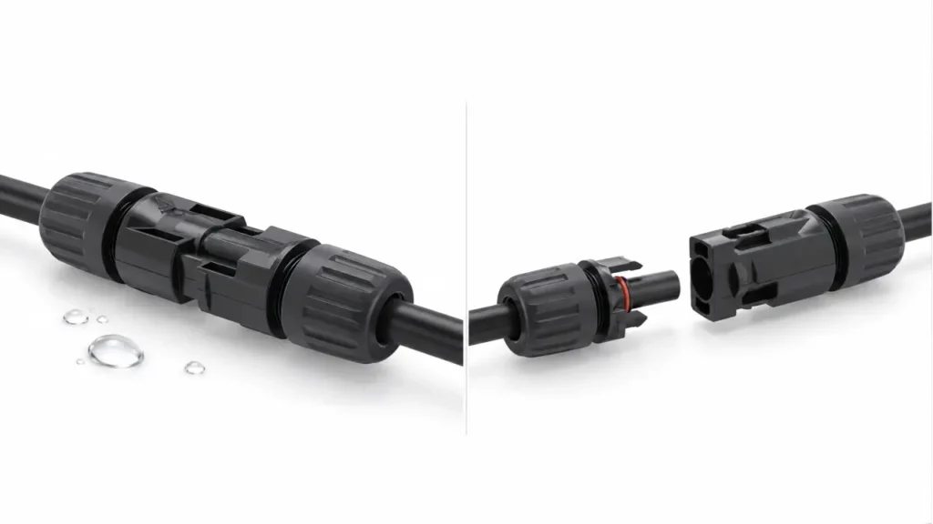
For example, current MC4-Evo 2 documentation specifies:
Mated: IP65 / IP68 under stated test conditions
Unmated: IP2X
This immediately shows why saying simply:
“MC4 connectors are IP68 waterproof”
can be misleading.
The protection applies to a particular product in a defined condition.
Mated vs Unmated Matters
An assembled and fully mated connector can have substantially different ingress protection from two disconnected connector halves.
Protection also depends on correct:
- cable diameter
- seal selection
- gland assembly
- tightening procedure
- mating engagement
- component condition
A damaged seal or cable outside the specified diameter range can compromise the connection even if the connector model itself has an IP68 rating.
IP68 Does Not Automatically Mean “Better Connector”
IP67 and IP68 describe ingress-protection test classifications.
They do not independently tell you:
- contact resistance
- current capability
- mechanical durability
- UV performance
- cable compatibility
- cross-mating compatibility
- long-term field reliability
For purchasing, IP rating is one requirement—not an overall connector quality score.
Contact Resistance: Small Number, Important Meaning
Every electrical connection introduces resistance.
In a PV connector, excessive contact resistance can contribute to:
- power loss
- localized heating
- thermal cycling
- accelerated degradation
But another common mistake is to copy a generic value such as:
≤ 0.5 mΩ
and call it an industry-wide MC4 specification.
Contact resistance belongs to the exact connector design and test conditions.
For example, current Original MC4 documentation states a maximum connector contact resistance of 0.25 mΩ for that specified product family.
That value should not automatically be assigned to third-party PV connectors.
Lower on Paper Does Not Automatically Mean Better in the Field
A supplier quoting an unusually low initial contact-resistance value has not necessarily demonstrated long-term connector quality.
A useful technical evaluation also considers what happens after:
- thermal cycling
- mechanical loading
- environmental exposure
- aging
- repeated mating
- cable movement
For buyers, the test method and supporting documentation matter more than simply choosing the smallest number in a comparison table.
Contact Material and Plating
Tin-plated copper contacts are widely used in photovoltaic connectors.
Other products may use different plating systems, including silver-plated contacts.
Plating influences characteristics such as:
- contact interface behavior
- corrosion resistance
- insertion characteristics
- manufacturing cost
But plating should not be evaluated independently from the complete connector system.
A silver-plated contact is not automatically a better connector if the crimp geometry, spring interface, sealing system or manufacturing consistency is poor.
Likewise, do not assume that every black PV connector uses the same contact material.
Use the exact product specification.
Connector Housing Material
Older generic online specification tables often state:
Insulation material: PPO
as though PPO were part of the definition of an MC4 connector.
That is incorrect.
Different connector families can use different engineering polymers.
For example, current Stäubli documentation includes products using PA as insulation material, while other PV connector designs use PC, PPO or other qualified materials depending on product design.
The correct procurement question is therefore not:
“Is MC4 made from PPO?”
It is:
“What insulating material is used in this exact connector, and what environmental and flame-performance data support its intended application?”
Temperature Ratings: Do Not Mix Three Different Numbers
Connector datasheets may contain several temperature specifications.
These are not interchangeable.
Ambient Temperature Range
The environmental temperature range in which the connector is intended to operate.
Upper Limiting Temperature
A product-specific maximum temperature defined under the applicable testing framework.
Rated Current at a Defined Temperature
Some current values are associated with specific ambient or conductor conditions.
This is why copying:
Operating temperature: −40°C to +125°C
from one catalog into another connector specification can be misleading.
Use the actual product’s tested and documented range.
IEC 62852 and UL 6703: What They Mean
For professional PV procurement, standards and certification language should be read carefully.
IEC 62852
IEC 62852 covers safety requirements and tests for connectors used in DC photovoltaic circuits. Its scope includes products with rated voltages up to 1500 V DC and rated currents up to 125 A per contact.
Official source:
IEC 62852 official publication
This does not mean:
IEC 62852 connector = automatically 1500 V / 125 A.
Those are scope limits of the standard.
The exact approved rating still belongs to the product.
UL 6703
UL Solutions identifies UL 6703 as the Standard for Connectors for Use in Photovoltaic Systems and UL 6703A as applying to PV connector applications within its solar-component certification services.
Official source:
UL Solutions — Solar Materials and Components Certification
This is particularly relevant when evaluating products for the North American market.
Standard, Certificate and Certification Body Are Not the Same Thing
Do not treat these expressions as synonyms:
IEC 62852 — a technical standard
UL 6703 — a technical standard used in North American certification
TÜV Rheinland — a testing and certification organization
A supplier should be able to identify:
- the standard
- certificate number where applicable
- exact models covered
- ratings covered by that certification
A generic company certificate does not prove that every connector in a catalog carries the same approval.
How to Read an MC4 Connector Specification Sheet
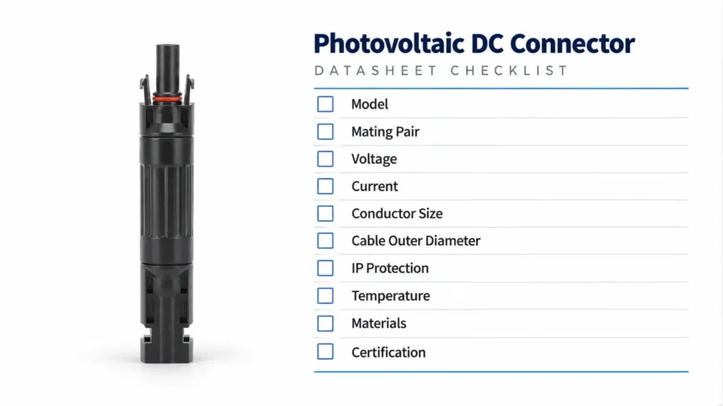
When comparing two suppliers, read the datasheet in this order.
1. Identify the Exact Model
Do not begin with the marketing name.
Find the connector series and model number.
2. Check the Intended Mating Counterpart
The mating connector is part of the connection system.
Physical fit alone does not establish approved compatibility.
3. Check Rated Voltage
Confirm that the exact model is approved for the intended system voltage.
4. Match Rated Current to Cable Size
Do not use the highest current printed anywhere on the datasheet if your chosen conductor size corresponds to another rating.
5. Check Both Cable Measurements
Verify:
conductor cross-section
and
cable outside diameter.
6. Check the IP Condition
Determine whether the stated IP rating applies:
mated
or
unmated
and under what test conditions.
7. Check Termination Requirements
Confirm:
- contact type
- strip length
- crimp die
- assembly procedure
- gland tightening requirement
For field termination, see How to Crimp MC4 Connectors.
8. Verify the Actual Certification
Request documentation for the exact connector model and rating needed for the project.
A Better Specification Request for PV Connector Suppliers
Instead of sending a supplier:
“Please quote MC4 1500V 50A.”
a professional inquiry should contain more information.
For example:
Product function: inline PV cable connector
Required voltage class: 1500 V DC
Required conductor: 6 mm²
PV cable outer diameter: actual cable OD
Required current: project requirement
Mating counterpart: exact connector system
Installation market: United States / EU / other
Required standard or certification: project-specific
Termination: field crimp or pre-assembled
Documentation: datasheet, assembly instruction and applicable certificate
This produces much more comparable quotations.
It also reduces the risk of two suppliers offering visually similar products that are technically different.
UHCCY connector platforms and available configurations can be reviewed in the Solar Connector category.
Key Takeaway
The phrase MC4 connector specifications does not describe one universal table of numbers.
A useful connector specification always answers:
Which model?
With which cable?
Under which certification basis?
In which assembled condition?
That leads to five practical rules:
- Never assume all MC4-looking connectors have the same current or voltage rating.
- Match rated current to the exact conductor size and product documentation.
- Check cable outer diameter as well as conductor cross-section.
- Read IP ratings together with mated/unmated conditions.
- Verify standards and certificates against the exact model being purchased.
If a datasheet cannot answer those questions, the connector has not yet been specified well enough for professional procurement.