Table of Contents
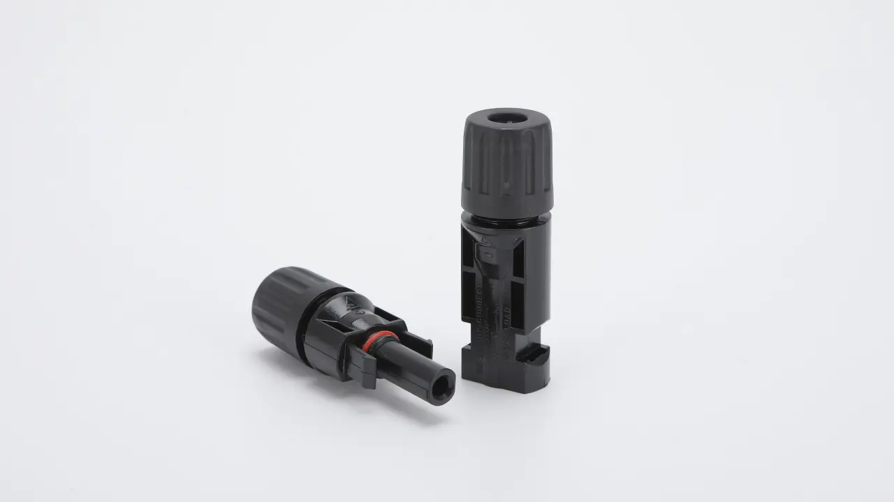
MC4 is one of the most widely searched terms for connectors used in photovoltaic systems, but it is also one of the most loosely used.
The Original MC4 is a photovoltaic connector system developed by Multi-Contact, now Stäubli Electrical Connectors. In everyday solar discussions, however, “MC4 connector” is often used more broadly for similar-looking locking PV connectors from different manufacturers.
That distinction matters.
A connector may look similar, use a 4 mm contact system, or even physically mate with another connector without being an Original MC4 or being approved for cross-mating with it.
This guide explains what MC4 actually means, how this type of PV connection works, which specifications matter, how polarity and connector gender should be understood, and what installers and buyers should verify before approving a connection.
If you are sourcing third-party photovoltaic connectors rather than looking specifically for the Original MC4 system, see the UHCCY Solar Connector range.
What Is an MC4 Connector?
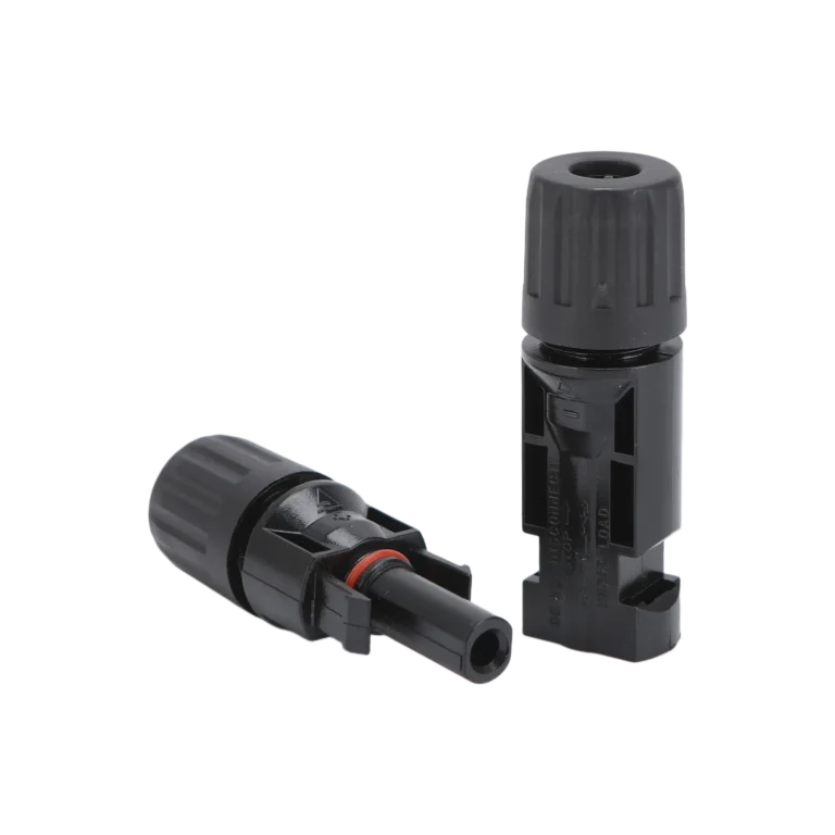
The Original MC4 is a single-pole DC connector system designed for photovoltaic wiring.
It creates a locking, insulated connection between PV conductors while protecting the electrical contact from accidental touch and environmental exposure when correctly assembled and mated.
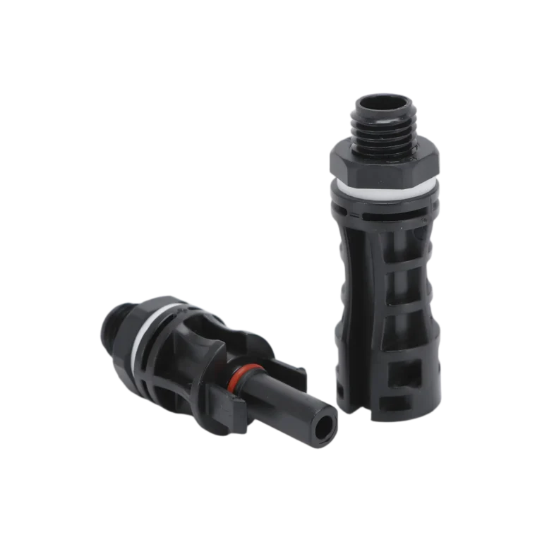
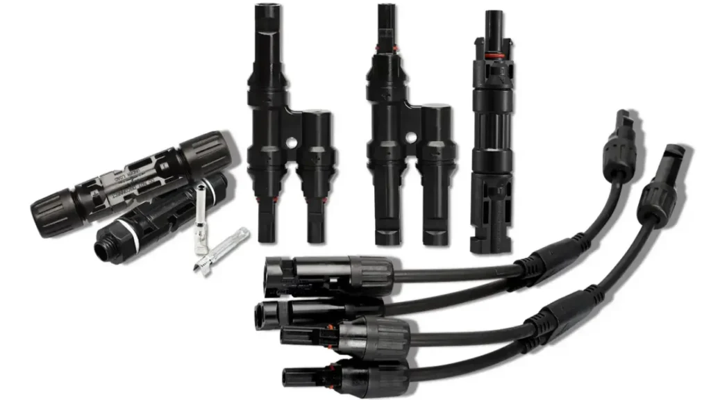
The basic connection consists of a conductive contact, insulated housing, cable sealing components and a locking interface. Depending on the product family, related configurations may also include panel receptacles, branch connectors, in-line fuse connectors and other PV connection components.
The important point is that the black plastic housing is only part of the connection.
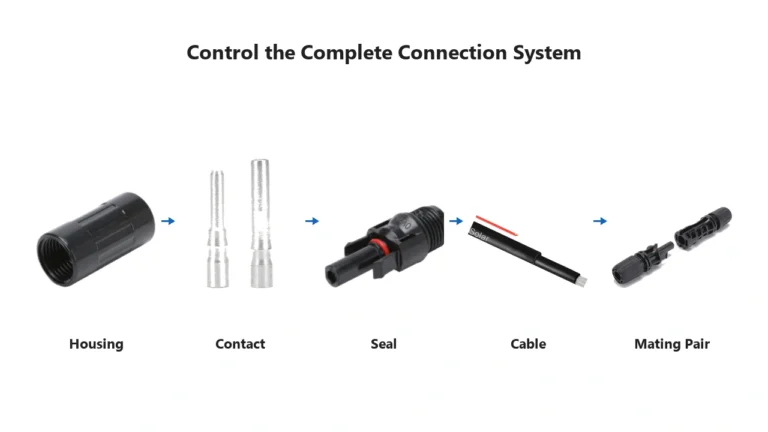
A reliable PV connection depends on the complete system:
cable → conductor → crimp contact → housing → seal → mating connector
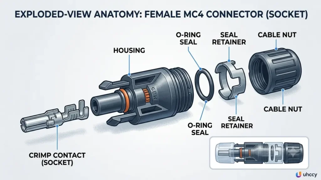
If one of those elements is incorrect, the fact that the two housings can click together does not guarantee a reliable connection.
That is the first principle we recommend using when evaluating any solar connector.
What Does MC4 Stand For?
“MC” comes from Multi-Contact, the company that originally developed the connector family and later became part of Stäubli.
The “4” refers to the approximately 4 mm contact system used by the connector.
This history is also why MC4 should not be treated as a generic product name for every photovoltaic connector with a similar appearance.
For third-party products, terms such as solar connector, PV connector or photovoltaic connector are more accurate unless the product is genuinely part of the Stäubli MC4 family or has specifically documented intermatability.
MC4 Is a Product Family, Not a Universal Specification
One of the most common mistakes in solar connector selection is assuming that “MC4” automatically tells you the connector’s voltage, current, cable size and environmental rating.
It does not.
Those values belong to a specific connector model and configuration.
For example, conductor cross-section alone can change the current rating of the same connector family. Current Stäubli MC4-Evo 2 technical data lists different IEC current ratings for 2.5 mm², 4 mm², 6 mm² and 10 mm² conductors.
That illustrates an important point:
There is no reliable universal rule such as “an MC4 connector is always 30 A.”
When evaluating a PV connector, use the datasheet for the exact product being installed rather than a generic MC4 specification copied from another connector.
How an MC4-Type PV Connection Is Built
Although designs differ between manufacturers and connector families, a field-assembled PV cable connector normally contains several functional elements.
| Component | Function | What to verify |
|---|---|---|
| Insulated housing | Protects and positions the electrical contact | Correct mating family, material and locking condition |
| Metal contact | Carries current between conductors | Correct contact for conductor size and connector model |
| Contact retention | Holds the crimped contact in the housing | Contact is fully seated and cannot move out of position |
| Cable seal | Seals around the cable jacket | Cable outside diameter is within the specified range |
| Cable gland / nut | Compresses the seal and provides strain relief | Correct assembly and tightening procedure |
| Locking interface | Prevents unintended separation | Fully engaged and undamaged |
The connection should therefore be selected and assembled as a system, not as a collection of interchangeable plastic parts.
A correct housing combined with the wrong contact, cable diameter or crimp geometry can still create a poor connection.
Male, Female, Positive and Negative Are Not the Same Thing
This is another area where PV connector terminology creates unnecessary confusion.
Male/female describes the connector interface. Positive/negative describes electrical polarity.
They are not interchangeable concepts.
To make things more confusing, connector manufacturers may describe the housing and the internal metal contact differently. A housing that appears “male” externally can contain a socket contact, while another housing can contain a pin contact.
For this reason, connector gender should never be used as the only way to determine polarity.
When working with an existing PV module or cable assembly, verify polarity from the equipment markings and the manufacturer’s documentation. Where appropriate, qualified personnel can also confirm polarity with suitable test equipment before making the final connection.
The practical rule is simple:
Identify polarity electrically and by markings—not by the shape of the housing alone.
For a more detailed explanation of series and parallel connections, see the MC4 Connector Wiring Guide.
What Specifications Actually Matter?
A buyer or installer should look at several parameters together rather than selecting a connector from one headline rating.
| Parameter | Why it matters |
|---|---|
| Rated DC voltage | Must be suitable for the maximum voltage of the intended PV system |
| Rated current | Depends on the connector design, conductor size, operating conditions and certification basis |
| Conductor cross-section | Determines whether the contact is suitable for the cable conductor |
| Cable outside diameter | Determines whether the gland and seal can properly grip and seal the cable |
| Contact resistance | Influences electrical loss and heat generation at the connection |
| Temperature range | Must be suitable for the installation environment and connector application |
| Degree of protection | Applies under the conditions defined by the manufacturer, normally including correct assembly and mating |
| Contact material and plating | Affect conductivity, corrosion behaviour and long-term contact performance |
| Applicable standards / certifications | Must correspond to the exact model and intended market |
Current Rating
Current rating deserves particular attention.
A connector does not carry current independently of the cable and contact. The conductor size, contact geometry, ambient conditions and applicable testing standard can all affect the published rating.
For that reason, a 4 mm² version and a 6 mm² version of the same connector platform may legitimately have different rated currents.
Never select a replacement simply because both products are described online as “MC4 30A” or “MC4 50A.”
Voltage Rating
The connector’s rated voltage must be appropriate for the PV system in which it is used.
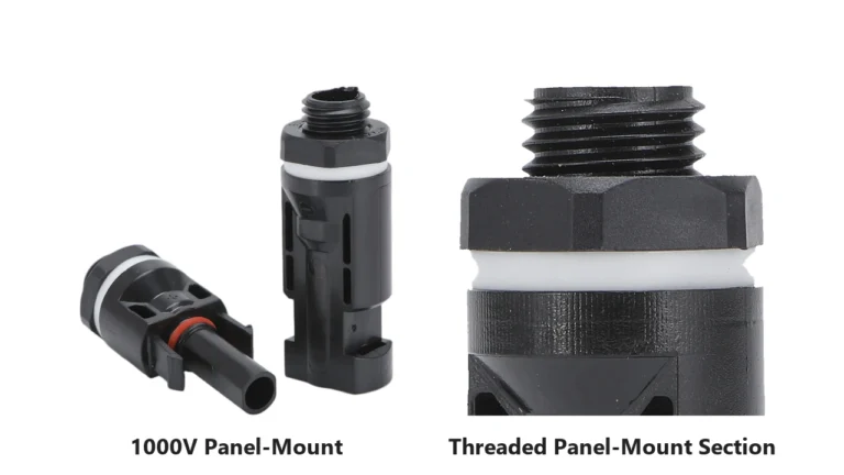
Modern PV connector families can be available for different system voltage classes, including products intended for 1000 V DC and 1500 V DC systems.
However, the physical appearance alone does not establish the voltage rating.
Always verify the exact model.
IP Rating
Another common shortcut is to describe all MC4-style connectors as “IP67 waterproof.”
That is too simple.
An ingress-protection rating applies under specific test and assembly conditions. A connector may have one degree of protection while properly mated and a very different protection level while unmated.
The cable seal also depends on using a cable with an outside diameter that falls within the connector’s specified sealing range.
This is why cable outside diameter matters in addition to conductor cross-section.
Physical Compatibility Is Not the Same as Approved Intermatability
Two connectors can physically fit together and still be the wrong combination.
Small differences in contact geometry, spring force, plating, seal dimensions and manufacturing tolerances can change the electrical and environmental performance of the completed connection.
For U.S. PV installations, NEC requirements on mating connectors are particularly important. Where connectors are not of identical type and brand, documented intermatability becomes a compliance issue rather than something that should be judged simply by whether the parts can be pushed together.
The 2026 NEC further strengthens this concept by requiring appropriate documentation from both manufacturers when non-identical connector systems are intended to be intermated.
International PV installation guidance also places strong emphasis on avoiding undocumented cross-mating.
For installers and buyers, the practical rule is:
“It fits” is not evidence of compatibility.
Before combining two different connector families, verify the manufacturers’ documentation and the applicable listing or certification requirements for the project.
Common PV Connector Configurations
“MC4 connector types” is often searched as though every related PV component were simply another version of one connector. A more useful way to understand the market is by function.
| Configuration | Typical function |
|---|---|
| Cable connector pair | Straight cable-to-cable or module wiring connection |
| Panel-mount connector | Creates a fixed connection point through an enclosure or equipment panel |
| Branch connector | Combines parallel PV conductors or strings |
| In-line fuse connector | Integrates overcurrent protection into a PV connection |
| Diode connector | Integrates a diode for a specific circuit function |
| Pre-assembled extension cable | Extends PV wiring without field termination at both ends |
For a more detailed comparison, see MC4 Connector Types Explained.
The key selection question is not “Which MC4 shape do I need?” but:
What electrical function must this connection perform, and what current will pass through it?
That becomes especially important with branch connectors because parallel circuits increase current on the combined side.
Series and Parallel Connections
PV connectors are commonly used in both series and parallel arrangements, but the electrical result is different.
In a series string, module voltages add while the string current remains approximately the current of one module.
In a parallel arrangement, current from the parallel branches adds while voltage remains approximately the same.
That means a connector used downstream of multiple parallel branches may carry substantially more current than a connector on one individual module lead.
The connector, cable and overcurrent protection therefore need to be evaluated together.
The MC4 Connector Wiring Guide explains this relationship in more detail.
How Should a Field-Assembled PV Connector Be Installed?
Installation instructions should always come from the manufacturer of the exact connector being used. Generic strip lengths, torque values and tool settings should not be copied from another brand.
A typical crimped PV connector workflow looks like this:
| Stage | What matters |
|---|---|
| Select | Match connector, contact, conductor cross-section and cable outside diameter |
| Prepare | Install sealing and gland components in the sequence specified by the manufacturer |
| Strip | Remove the specified insulation length without damaging conductor strands |
| Crimp | Use the specified contact and appropriate crimping die/tool |
| Insert | Push the contact into the housing until the retention mechanism is fully engaged |
| Seal | Tighten the cable gland according to the manufacturer’s instructions |
| Mate | Connect only the intended mating pair and confirm the locking mechanism is engaged |
| Verify | Confirm polarity, mechanical retention and correct installation before energizing |
Do not assume that a connector designed to carry operating current is also intended to interrupt that current.
PV connectors should not be disconnected under load unless the specific connector and system are designed and approved for that function.
For the full termination procedure, see How to Crimp MC4 Connectors.
Why PV Connectors Fail
A connector failure is often described simply as a “bad connector,” but the connector itself is only one possible cause.
| Failure mechanism | Typical issue to investigate |
|---|---|
| Poor crimp | Wrong die, damaged strands, incorrect contact or incomplete crimp |
| Cross-mated connectors | Different systems combined without documented intermatability |
| Wrong cable diameter | Seal cannot compress correctly around the cable jacket |
| Incorrect gland assembly | Insufficient sealing or mechanical strain relief |
| Incomplete mating | Locking interface not fully engaged |
| Contamination | Dirt or moisture introduced before mating |
| Mechanical stress | Cable tension, unsupported connectors or excessive bending |
| Electrical overload / high resistance | Excessive heating at the contact interface |
A small increase in connection resistance may not immediately stop a PV system from operating. Instead, it can create localized heating that develops over time.
For this reason, visual condition, correct assembly, cable management and connector consistency across a string are important parts of system reliability.
Any connector showing melting, discoloration, cracking, damaged locking features or signs of overheating should be investigated rather than simply pushed back together.
For Buyers: Approve the Connection System, Not Just the Housing
Bulk buyers often compare PV connectors by unit price and headline electrical ratings.
That misses several of the details that determine whether the connector will work correctly with the actual cable and project.
Before approving a connector for repeat purchasing, ask the supplier to confirm:
| Information | Why you need it |
|---|---|
| Exact connector model and mating counterpart | Prevents mixing different connector families |
| Rated voltage and current by conductor size | Avoids applying one rating to every cable configuration |
| Conductor cross-section range | Confirms the electrical contact fits the cable |
| Cable outside-diameter range | Confirms the sealing system fits the cable jacket |
| Contact material and plating | Helps evaluate electrical and corrosion performance |
| Applicable certificate and exact models covered | Prevents generic company certificates being mistaken for product approval |
| Assembly instruction | Defines strip length, tooling, insertion and tightening requirements |
| Recommended crimp tool / die | Helps maintain repeatable terminations |
| Product marking and traceability | Helps distinguish batches and identify components later |
| Samples with the intended cable | Allows the actual cable-connector combination to be evaluated before a bulk order |
This is especially important for OEM projects.
A connector can pass a visual inspection and still be the wrong configuration for the cable being used.
For procurement, the cable and connector should therefore be specified together wherever possible.
MC4 and UHCCY Solar Connectors
UHCCY uses Solar Connector and PV Connector as the product names for its own photovoltaic connector platforms.
“MC4” is used in this guide because it refers to the Original Stäubli product family and because it is a widely searched term used by people researching this style of PV connection.
UHCCY products should not be assumed to be Original MC4 products or approved for cross-mating with Stäubli products unless specific documentation establishes that relationship.
For UHCCY connector specifications, available voltage classes, cable sizes and connector configurations, use the Solar Connector category as the primary product reference.
Key Takeaway
The most useful way to understand an MC4 or similar PV connector is not as a black plastic plug.
It is an engineered connection system.
The housing, contact, cable conductor, cable outside diameter, crimp, seal, mating counterpart and applicable certification all work together.
That leads to four practical rules:
- Use the datasheet for the exact connector instead of relying on generic “MC4 specifications.”
- Do not use connector gender alone to determine electrical polarity.
- Do not treat physical mating as proof of approved intermatability.
- Select the connector and cable as one system, especially for bulk purchasing and project standardization.