Table of Contents
An MC4 inline fuse integrates a photovoltaic fuse holder directly into a PV cable connection so overcurrent protection can be installed in series with an individual solar string.
It can be a compact alternative to placing every string fuse inside a combiner box, but the presence of a fuse does not automatically make a PV circuit correctly protected.
The fuse link, fuse holder, connector interface, cable and PV module must all be coordinated.
That means selecting an inline fuse connector requires more than choosing a familiar amperage such as 15A or 20A.
A more useful selection sequence is:
PV module data → parallel-string configuration → required protection → fuse current → system voltage → fuse format → connector and cable compatibility
UHCCY uses Solar Connector or PV Connector for its own products; “MC4 inline fuse” is used here because it is a common search term for this type of PV component.
For other connector configurations, see Solar Connector.
What Is an MC4 Inline Fuse?
An MC4 inline fuse connector combines three functions in one cable-mounted assembly:
PV connection + fuse holder + replaceable fuse link
Instead of routing a string conductor into a DIN-rail fuse holder inside an enclosure, the fuse can be placed directly in the string wiring.
Typical applications include:
- individual PV string protection;
- localized protection before parallel combining;
- cable assemblies incorporating string fusing;
- compact photovoltaic systems where a separate combiner enclosure is unnecessary;
- OEM solar harnesses requiring integrated overcurrent protection.
The fuse itself remains a sacrificial protection component. If it operates, the fuse link must be replaced after the fault condition has been investigated and corrected.
An inline fuse connector should therefore not be treated as an ordinary connector with a fuse added for convenience. It is part of the PV protection system.
Why PV Strings Need Different Fuse Logic
PV modules behave differently from conventional power sources.
A single PV string is inherently current-limited by the modules. The more important overcurrent condition often appears when multiple strings are connected in parallel.
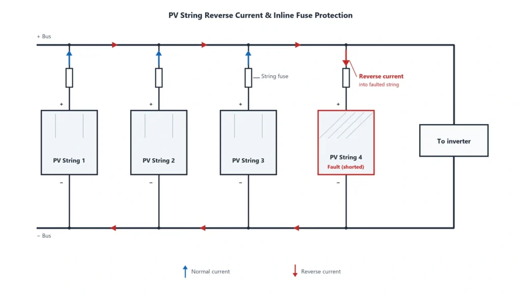
If one string develops a fault, healthy parallel strings can potentially feed reverse current into that faulted string.
Conceptually:
String A + String B + String C → parallel connection
If String A develops a suitable fault, current can be supplied toward it from Strings B and C.
The available reverse current therefore tends to increase as more sources are connected in parallel.
This is why PV string fuse selection is closely related to:
- module short-circuit current
Isc; - number of parallel strings;
- module maximum series fuse rating;
- cable ampacity;
- system architecture.
When Is an Inline Fuse Actually Required?
This is where many online explanations become too simplistic.
You will often see statements such as:
“Two parallel strings do not need fuses, but three strings always do.”
That can be a useful rule of thumb for some conventional PV configurations, but it is not a universal engineering rule.
The real question is whether current available from the other sources can exceed the permitted current of the faulted string, its conductors or connected equipment.
For U.S. installations, NEC 690.9 specifically recognizes situations where overcurrent protection is not required when the conductor has sufficient ampacity and currents from all sources cannot exceed the equipment’s permitted overcurrent protection level.
Therefore the number of strings alone is not enough.
Check:
Module Isc → parallel sources → possible reverse current → module Maximum Series Fuse Rating → conductor ampacity → applicable code
An inline fuse is useful only when the protection design requires a fuse at that point.
Adding an unnecessary fuse also adds:
- another resistive element;
- additional contact interfaces;
- another thermal source;
- another component requiring inspection and replacement.
So “more protection devices” does not automatically mean “better protection.”
For string-fuse requirements and sizing logic, see Solar Panel Fuse Guide.
How to Select the Correct Fuse Current
Do not select an inline fuse simply because:
“The connector is 30A, so I should install a 30A fuse.”
The connector current capability and fuse operating current are different parameters.
Start with the PV module datasheet.
Important values include:
Isc— short-circuit current;- maximum system voltage;
- Maximum Series Fuse Rating / Maximum OCPD Rating;
- applicable module installation instructions.
NEC-Based Current Sizing
For conventional PV source circuits designed under NEC rules, a commonly used calculation starts with:
Maximum circuit current ≈ 1.25 × Isc
The overcurrent device is then commonly sized to at least 125% of that maximum circuit current, producing the familiar starting relationship:
Fuse current ≥ 1.56 × Isc
Eaton and Littelfuse both use this approach in their PV fuse sizing guidance.
However:
1.56 × Isc is not a universal international fuse-selection formula.
The final selected fuse must also satisfy the upper limits.
In simplified form:
Minimum required fuse rating ≤ selected fuse ≤ module Maximum Series Fuse Rating
and the selected fuse must also coordinate with the conductor and holder.
Temperature Matters
Fuse links are thermal devices.
High ambient temperature can reduce their continuous current capability, particularly inside:
- rooftop installations;
- tightly grouped cable harnesses;
- enclosed fuse bodies;
- hot combiner boxes.
Manufacturer derating information therefore matters when operating close to the fuse rating.
Breaking Capacity Matters Too
A fuse is not specified only by:
voltage + amperage
It also has a rated breaking or interrupting capacity.
That rating must be suitable for the prospective fault conditions of the application.
For a broader range of PV fuse links and DIN-rail holders, see DC Fuse.
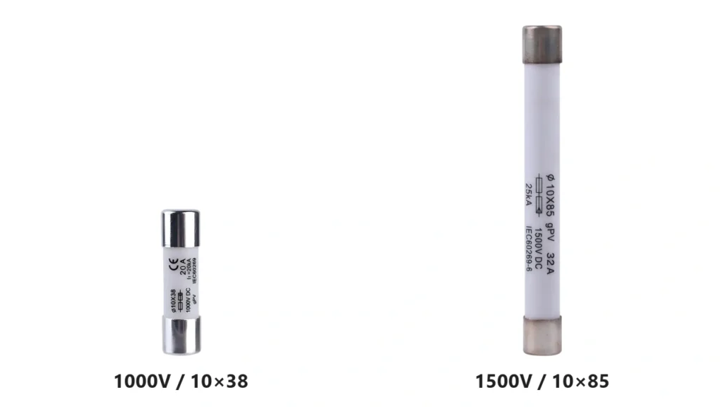
10×38 vs 10×85: What Fuse Size Really Means
Fuse dimensions describe the physical cartridge format.
They do not, by themselves, define the voltage rating.
This distinction matters because the market often associates:
10×38 → 1000V
and:
10×85 → 1500V
That association is common, but it is not universal.
Some manufacturers offer 1500V DC 10×38 PV fuse links, while 10×85 is also widely used for 1500V PV applications.
So this would be incorrect:
All 10×38 fuses are 1000V.
And this would also be incorrect:
Any 10×85 fuse is automatically suitable for 1500V PV.
Instead verify:
| Parameter | What Must Match |
|---|---|
| Fuse dimensions | Holder geometry |
| Rated voltage | Maximum PV circuit voltage |
| Rated current | Protection design |
| Fuse category | PV application |
| Breaking capacity | Prospective fault current |
| Temperature capability | Installation environment |
UHCCY Configurations
For UHCCY’s current connector range:
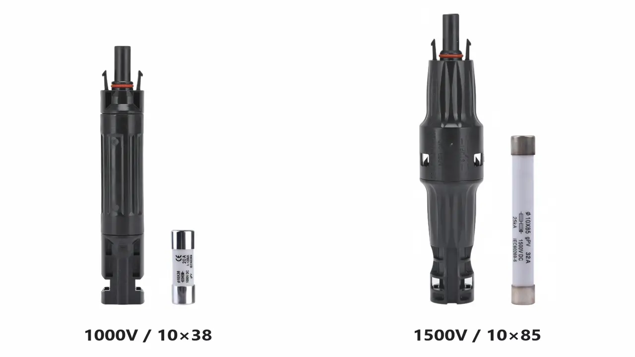
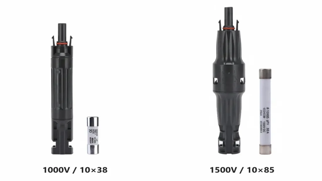
UH-PC-MF01 – 1000V Inline Fuse Solar Connector uses a 10 × 38 mm PV fuse.
UH-PC-MF02 – 1500V Inline Fuse Solar Connector uses a 10 × 85 mm PV fuse.
These are UHCCY model specifications, not universal rules for every manufacturer’s fuse connector.
UH-PC-MF01 is documented as a 1000V DC connector with a 10×38 mm replaceable fuse chamber, while UH-PC-MF02 uses the longer 10×85 mm format for its 1500V platform.
1000V vs 1500V Inline Fuse Connectors
Increasing the system voltage changes more than the fuse cartridge length.
The complete inline assembly must be suitable for the maximum DC voltage that can occur in the PV string.
That includes:
Fuse link → internal fuse contacts → insulation → connector housing → mating connector → cable
A 1500V fuse installed inside a 1000V-rated holder does not create a 1500V assembly.
Likewise, a 1500V connector housing does not make an incorrectly rated fuse suitable for the system.
Maximum PV string voltage should also account for the increase in module open-circuit voltage at low temperature.
For broader connector-voltage considerations, see 1000V vs 1500V Solar Connectors.
gPV Fuse vs an Ordinary DC Fuse
A fuse labelled simply as a DC fuse is not automatically equivalent to a photovoltaic fuse.
PV systems can produce fault conditions involving relatively low but sustained reverse currents, so fuse behavior has to suit photovoltaic applications.
For IEC-oriented systems, IEC 60269-6 defines supplementary requirements for fuse-links protecting PV strings and arrays at nominal circuit voltages up to 1500V DC. See IEC 60269-6.
The common IEC utilization category is:
gPV
For North American PV fuse applications, UL 248-19 is the dedicated photovoltaic fuse standard. Its November 2024 revision expanded the standard’s maximum PV voltage scope to 2000V DC. See UL 248-19.
There is an important B2B compliance distinction here:
Fuse certification and connector certification are not the same thing.
An inline fuse assembly may include:
- a fuse evaluated under PV fuse requirements;
- a connector interface evaluated under PV connector requirements;
- a housing that forms the fuse holder.
A certificate for the fuse link alone should therefore not be presented as proof that the complete inline connector assembly carries the same certification.
This should be checked at the exact model level.
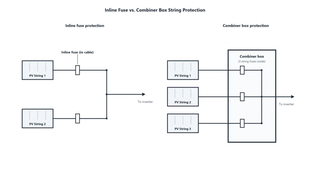
Inline Fuse Connector vs Combiner Box Fuse Holder
Both can protect individual PV strings, but they solve the installation problem differently.
Inline Fuse Connector
Useful when:
- localized protection is required in the cable run;
- the number of fused strings is limited;
- a compact assembly is preferred;
- a preassembled OEM cable harness is being produced;
- adding a complete combiner enclosure would be unnecessary.
Combiner Box / DIN-Rail Fuse Holder
Often more appropriate when:
- many strings need individual protection;
- fuse replacement needs to be centralized;
- DC SPD is required;
- an isolator or breaker is included;
- string monitoring is required;
- larger output conductors are being terminated;
- organized maintenance access is important.
The distinction is therefore not:
small system = inline fuse
and:
large system = combiner box
Instead ask:
Where should string protection be located so it can be correctly rated, inspected and serviced?
Installation, Polarity and Fuse Replacement
An inline fuse holder should not automatically be treated as a disconnect switch.
Before opening the holder or replacing the fuse:
isolate the relevant PV circuit and remove load current according to the system shutdown procedure.
Your current UHCCY MF01 and MF02 product instructions already specify that the circuit must be isolated and that the fuse connector should not be opened under load.
Installation should also confirm:
- correct fuse format;
- correct fuse rating;
- correct polarity;
- complete fuse seating;
- properly closed housing;
- fully engaged connector lock;
- intact sealing surfaces;
- mechanical cable support.
Which Polarity Should Be Fused?
Do not turn “install the fuse in the positive cable” into a global rule.
Whether protection is placed in one polarity or both depends on:
- system grounding;
- PV architecture;
- applicable electrical code;
- equipment design.
Use the protection arrangement required by the system design.
After a Fuse Blows
Do not simply replace it with:
the same fuse repeatedly
or:
the next larger amperage.
First determine why it operated.
Possible causes include:
- reverse current from parallel strings;
- cable fault;
- connector fault;
- incorrect fuse sizing;
- equipment fault;
- insulation failure.
A larger fuse can remove the intended protection instead of solving the underlying problem.
Connector Compatibility and Thermal Reliability
An inline fuse connector still has to mate with another PV connector.
Adding a fuse does not remove the compatibility issue discussed in MC4 Connector Compatibility.
Do not assume compatibility because:
- both connectors are described as MC4;
- the housings physically engage;
- both are rated 1500V;
- the same cable size is used.
The exact mating system still matters.
The Fuse Also Adds Thermal Interfaces
Compared with a simple inline connector, a fuse assembly introduces additional electrical interfaces:
cable termination → connector contact → fuse-holder contact → fuse link → fuse-holder contact → connector contact
Every contact interface must maintain low resistance.
Poor contact pressure, contamination, incorrect fuse dimensions or thermal cycling can create localized heating.
The fuse link itself also dissipates power during normal operation, and manufacturers may specify current derating with elevated ambient temperature.
This is one reason a high-quality fuse link inside a poorly designed holder does not automatically produce a reliable assembly.
The fuse + holder + connector + cable should be evaluated together.
How to Specify an Inline Fuse Connector for B2B Purchasing
A request such as:
“Need 15A MC4 fuse connector.”
leaves too many variables undefined.
A useful RFQ should specify:
| Requirement | Example of What to Define |
|---|---|
| Connector function | Inline replaceable PV fuse |
| System voltage | 1000V DC / 1500V DC |
| Fuse format | 10×38 / 10×85 / project-specific |
| Fuse current | Selected from project design |
| Fuse category | gPV or required market standard |
| Breaking capacity | Required project value |
| Cable conductor | e.g. 4 mm² |
| Cable OD | Actual cable diameter |
| Mating counterpart | Exact connector manufacturer/model |
| Protection degree | Required environmental rating |
| Ambient temperature | Project conditions |
| Fuse supplied? | Holder only / holder + specified fuse |
| Certification | Exact required certification and model scope |
| OEM marking | Logo / model / packaging requirements |
One detail deserves particular attention:
Ask whether the quotation includes the fuse link or only the fuse holder connector.
Products that look identical in online listings may be supplied as:
holder only
or:
holder + 10A / 15A / 20A / other fuse
That affects both price and specification.
For standard PV fuse links and enclosure-mounted holders, compare the DC Fuse range.
For fused connector assemblies, start from Solar Connector.
Key Takeaway
An MC4 inline fuse is not simply a connector with an amperage number printed on it.
Correct selection follows:
PV circuit → need for OCPD → fuse current → maximum voltage → fuse format → breaking capacity → holder → cable → mating connector
The most important points are:
- Not every PV string automatically requires an inline fuse.
- Parallel-string reverse current is one of the main reasons string protection may become necessary.
- Fuse current should be derived from the PV protection design, not the connector’s current rating.
- The module Maximum Series Fuse Rating is an important upper limit.
- 10×38 and 10×85 describe physical fuse formats, not universal voltage classes.
- A 1500V fuse does not make a 1000V holder suitable for 1500V.
- PV applications require an appropriate PV fuse specification such as gPV where applicable.
- Fuse and connector certifications must be verified separately for the exact assembly.
- Inline holders must not be opened under load unless specifically designed and rated for that function.
- For larger multi-string systems, a combiner-box fuse arrangement may provide better serviceability and system integration.
The useful buying question is therefore not:
“Which MC4 fuse amperage do I need?”
It is:
“What protection does this PV string require, and which fuse, holder and connector assembly satisfies that complete requirement?”