Table of Contents
A solar panel fuse protects photovoltaic wiring and modules when a PV circuit can be exposed to more current than it is designed to carry. However, not every solar panel or every PV string automatically requires an individual fuse.
The important question is not simply how many panels are installed. It is whether another source—such as parallel PV strings—can feed enough reverse or fault current into a circuit to exceed the conductor ampacity or the module manufacturer’s permitted overcurrent protection.
This guide explains when solar fuses are needed, why parallel strings create reverse-current risk, where PV fuses are normally installed, and which ratings must be checked before selecting a fuse.
For the wider principles behind DC voltage ratings, breaking capacity and gPV fuse construction, see our DC Fuse Guide.
What Is a Solar Panel Fuse?
A solar panel fuse is a DC-rated overcurrent protective device used in a photovoltaic circuit.
In larger PV systems, the more accurate term is often PV string fuse, because one fuse normally protects an entire series-connected string rather than one individual solar module.
Modules connected in series carry essentially the same string current. Connecting more modules in series increases string voltage, but it does not multiply current in the same way that parallel connections do.
The protection problem changes when several strings are connected in parallel.
A fault in one string can allow the remaining healthy strings to feed current backward into the faulted circuit. If that reverse current exceeds the safe limits of the module or conductor, overcurrent protection may be required.
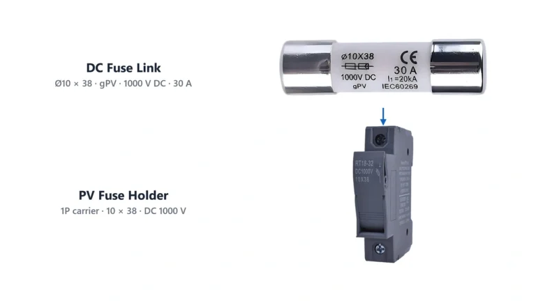
PV fuse-links designed specifically for this application are commonly classified as gPV fuses under IEC 60269-6.
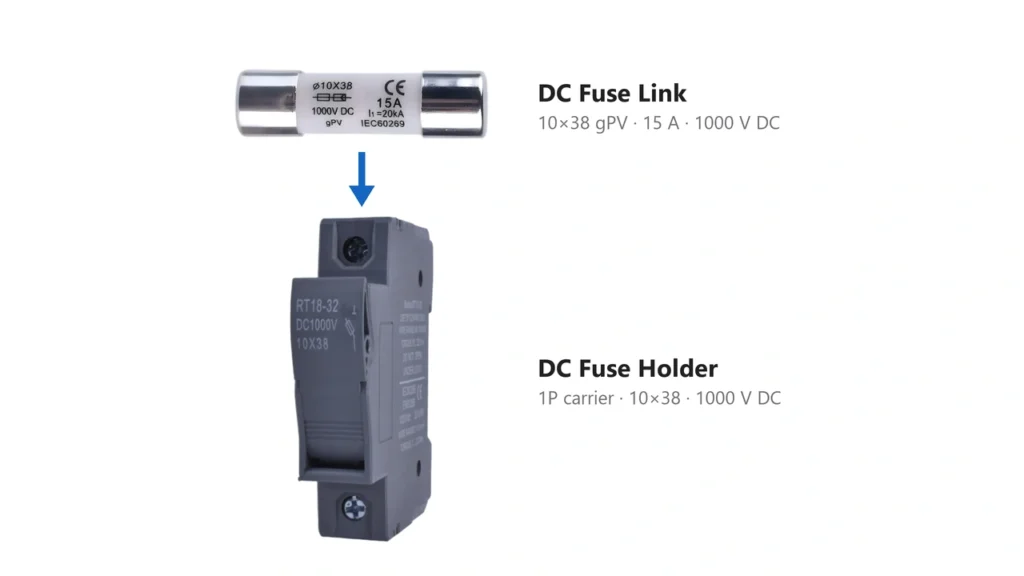
Solar panel fuse and gPV fuse holder for PV string protectionDoes Every Solar Panel Need a Fuse?
No.
A solar module does not require an individual fuse simply because it generates electricity.
Photovoltaic modules are current-limited sources. In a single string with no other source capable of feeding significant current back into the circuit, the available current may not be high enough to require separate string overcurrent protection.
The current edition of NFPA 70, National Electrical Code addresses PV overcurrent protection based on the available current from all sources, conductor ampacity and the maximum permitted overcurrent protection of the connected equipment.
The principle is more useful than a fixed rule:
A fuse becomes necessary when the possible current from connected sources can exceed what the conductor, PV module or other protected equipment is permitted to withstand.
That is why a simple statement such as:
“Every solar panel needs a fuse.”
is incorrect.
The opposite statement—
“Solar panels do not need fuses because their current is limited.”
—is also incomplete.
The actual requirement depends on the complete circuit.
When Does a Solar Panel Fuse Become Necessary?
The main concern in conventional PV arrays is usually reverse current from parallel strings.
Consider three identical PV strings connected in parallel.
Under normal operation:
String A →
String B → Combined output → inverter
String C →
Current from all three strings flows toward the inverter.
Now assume String A develops a fault.
String B and String C can potentially feed current toward String A instead of only toward the inverter.
The faulted string may therefore experience current originating from sources outside itself.
This is the condition that makes string overcurrent protection important.
The latest IEC PV array design requirements are contained in IEC 62548-1:2023+A1:2025, which covers PV array wiring, protection devices, switching and related DC safety requirements.
Why Parallel Solar Strings Create Reverse Current
Connecting modules in series and connecting strings in parallel have very different electrical effects.
In a series string:
- voltage increases;
- current remains approximately the current of one module.
In parallel strings:
- voltage remains approximately the string voltage;
- available current increases as additional strings are added.
This distinction is fundamental to fuse protection.
If one of several parallel strings develops a sufficiently low-resistance fault, the remaining strings become additional current sources.
A simplified worst-case concept is:
Reverse current into faulted string ≈ current contributed by the remaining parallel strings
For example, with three parallel strings:
String 1 = faulted
String 2 = current source
String 3 = current source
The faulted string may therefore receive current from two other strings.
The actual protection requirement still depends on module ratings, conductor capacity and system architecture rather than this simplified relationship alone.
For a detailed explanation of how series and parallel PV wiring affect voltage and current, see our MC4 Connector Wiring Guide.
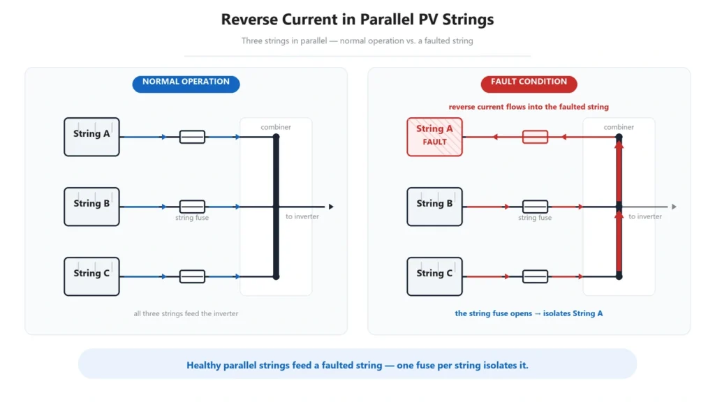
Solar panel fuse protection against reverse current in parallel PV stringsDo Three or More Parallel Strings Always Need Fuses?
Not as an unconditional rule.
You will often encounter guidance stating that:
- one string does not require string fusing;
- two parallel strings commonly do not require it;
- three or more parallel strings require fuses.
This is a useful rule of thumb, because three or more parallel strings create enough potential reverse-current contribution for string protection to become much more relevant.
Fuse manufacturers also use three-or-more-string examples when explaining photovoltaic string protection.
However, the engineering requirement should still be determined from:
available current from all sources → conductor ampacity → module maximum OCPD or series fuse rating → applicable electrical code
The NEC, for example, allows certain PV circuits to operate without separate OCPDs where the conductors have sufficient ampacity and the currents from all sources cannot exceed the maximum OCPD rating specified for the PV module or electronic power converter.
Therefore:
“Three strings = fuse required” should not replace an actual protection calculation.
It is better understood as the point at which individual string-fuse evaluation commonly becomes necessary.
What Is Maximum Series Fuse Rating?
Most photovoltaic module datasheets specify a value such as:
Maximum Series Fuse Rating: 20 A
or:
Maximum Overcurrent Protection Rating: 25 A
This value is extremely important.
It represents an upper protection limit defined for the module. It does not mean that the module should automatically be fitted with a fuse of that rating.
For example, if a module datasheet states:
- Isc: 13.8 A
- Maximum series fuse rating: 25 A
you cannot conclude from those two numbers alone that a 25 A fuse is correct.
The actual fuse must also satisfy:
- minimum required protection-device sizing;
- conductor ampacity;
- temperature conditions;
- system architecture;
- fuse manufacturer’s application requirements;
- applicable code requirements.
The maximum series fuse rating acts as an upper boundary, not a universal recommended fuse size.
This distinction is one of the most common sources of incorrect PV fuse selection.
How to Choose a Solar Panel Fuse
Correct solar fuse selection requires several parameters to be checked together.
1. Check the PV Module Isc
Isc, or short-circuit current, is one of the fundamental current values listed on a PV module datasheet.
It is used when determining expected maximum circuit current and overcurrent protection.
Do not select a fuse according to panel wattage alone.
Two modules with the same wattage can have different:
- operating voltage;
- operating current;
- short-circuit current;
- maximum series fuse rating.
Therefore, a search such as “what fuse for a 400 W solar panel?” does not contain enough information for a reliable answer.
2. Check the Maximum Series Fuse Rating
Find the module manufacturer’s maximum permitted fuse or OCPD rating.
The selected fuse must remain within that limit.
Never increase the fuse rating simply to prevent nuisance operation if doing so exceeds the module or conductor protection limit.
3. Calculate the Maximum Circuit Current
The protective device must carry expected operating current without unnecessary opening while still providing effective protection.
The required calculation depends on the governing standard or electrical code.
For NEC-based photovoltaic installations, fuse sizing involves the PV circuit maximum current and the applicable OCPD loading requirements.
Because this subject involves temperature correction, conductor coordination and code-specific calculations, it will be covered separately in our DC Fuse Sizing Guide rather than reduced to one universal multiplier here.
For manufacturer-based PV fuse calculation guidance, Littelfuse provides a dedicated photovoltaic fuse sizing guide.
4. Check DC System Voltage
Fuse voltage rating must be equal to or greater than the maximum voltage that can appear across the fuse.
For PV strings, this requires considering module open-circuit voltage and temperature effects.
Cold conditions can increase module Voc.
Therefore, a system described as “1000 V nominal” should not automatically be protected with a 1000 V fuse without confirming the calculated maximum system voltage.
UHCCY offers different fuse families for 1000 V and 1500 V PV architectures in the DC Fuse category.
5. Use a PV-Rated Fuse
A conventional fuse that physically fits the holder is not automatically suitable for photovoltaic protection.
PV systems present unusual fault conditions, including:
- sustained DC voltage;
- no natural AC current zero crossing;
- relatively low fault-current levels in some string faults;
- continuous outdoor operation;
- elevated combiner-box temperatures.
PV fuse-links are designed and tested specifically for these conditions.
IEC identifies photovoltaic fuse-links through the gPV utilization category.
For North American applications, UL 248-19 specifically addresses photovoltaic fuses used for protecting PV strings, arrays and associated wiring.
6. Verify Breaking Capacity
Rated current and breaking capacity are not the same thing.
A 20 A fuse is not limited to interrupting only 20 A.
The rated current describes its normal current classification and operating characteristic.
Breaking capacity describes the maximum prospective fault current that the fuse can safely interrupt under its specified conditions.
This becomes particularly important where other sources can supply substantial fault current.
Do not select a fuse solely from:
Voltage + Amp Rating
The complete selection should include:
Voltage + Current + gPV Category + Breaking Capacity + Fuse Size + Holder Compatibility
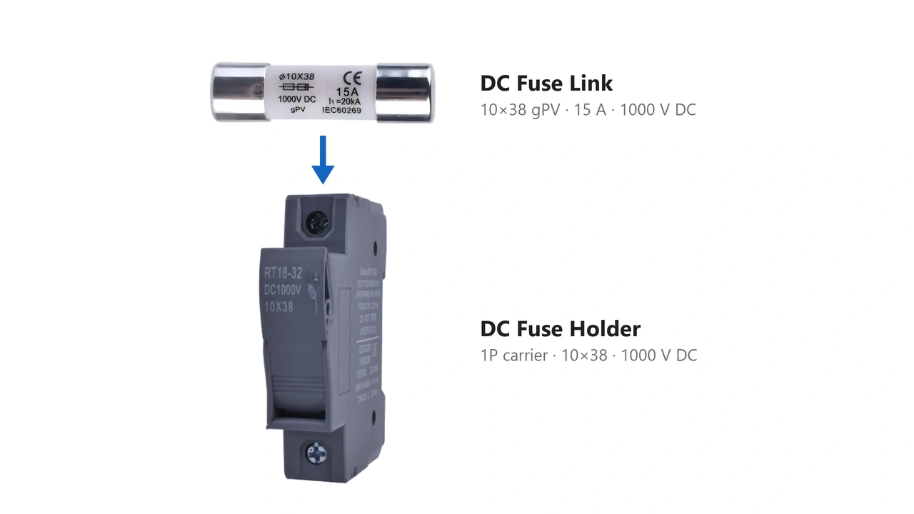
7. Match the Fuse Holder
The fuse link and holder form one protection assembly.
Check:
- fuse dimensions;
- rated DC voltage;
- current rating;
- terminal capacity;
- pole configuration;
- installation method;
- environmental conditions.
Common PV fuse formats include dimensions such as:
- 10 × 38 mm;
- 10 × 65 mm;
- 10 × 85 mm.
These sizes are not interchangeable.
For example, UHCCY currently uses different fuse-link and fuse-holder platforms for 1000 V and 1500 V systems. Exact combinations are listed on the DC Fuse category page.
Where Should Solar Fuses Be Installed?
PV string fuses are commonly installed where individual strings enter a combiner or other DC protection assembly.
A typical architecture is:
PV String 1 → Fuse →
PV String 2 → Fuse → Combiner → DC Output → Inverter
PV String 3 → Fuse →
This location allows a faulted string to be isolated from current supplied by the other parallel strings.
Depending on the system design, fuses may be installed in:
- PV combiner boxes;
- string protection enclosures;
- inverter-integrated combiner sections;
- appropriately designed in-line fuse assemblies.
The exact polarity requiring protection depends on system grounding, protection architecture and applicable installation rules.
Do not assume every system requires identical fusing of both positive and negative conductors.

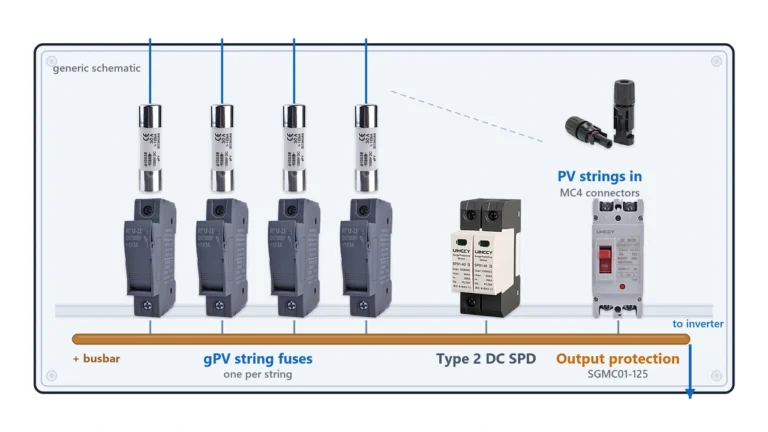
Solar panel fuse location for parallel PV strings in a combiner boxCan One Fuse Protect Several Solar Panels?
Yes—if those modules form one series string.
A string fuse does not normally protect one module individually.
For example:
10 modules connected in series → one PV string → one string protection circuit
All ten modules carry approximately the same string current.
Increasing the number of modules in series primarily increases voltage, so the number of panels alone does not determine fuse amperage.
This is why statements such as:
“Use one 15 A fuse for every five panels.”
have no general technical basis.
The correct protection depends on the electrical characteristics of the modules and circuit, not an arbitrary panel count.
Solar Fuse Size Is Not Based on Panel Wattage
This point deserves emphasis because it is a frequent search query.
A panel’s power rating follows approximately:
Power = Voltage × Current
The same power can therefore be produced through different voltage/current combinations.
A 400 W panel might operate at a significantly different current from another 400 W module.
Consequently:
Panel wattage → not enough information
A proper fuse-selection starting point requires at least:
Isc + maximum series fuse rating + number of parallel strings + system voltage
and then requires coordination with the conductor and applicable protection rules.
The cable itself must also be suitable for the resulting current, voltage drop and installation conditions. See our Solar Cable page for the related cable-selection considerations.
Solar Panel Fuse vs DC Circuit Breaker
Fuses and DC circuit breakers can both provide overcurrent protection, but they are not interchangeable simply because their current ratings match.
A PV fuse:
- uses a calibrated fusible element;
- must be replaced after operation;
- can provide high interrupting capability in a compact format;
- is available with PV-specific gPV characteristics.
A DC circuit breaker:
- uses a mechanical switching and trip mechanism;
- can normally be reset;
- may also provide manual isolation depending on its design;
- must be specifically rated for the relevant DC voltage and fault conditions.
Large PV protection systems often use multiple protection technologies at different levels.
For example:
String level → gPV fuse
Combined DC circuit → fuse or suitable DC circuit breaker
The correct architecture depends on system design and coordination requirements rather than a general claim that either technology is always better.
Inline Solar Fuse or Combiner Box Fuse?
Both configurations can be valid, but they serve different installation architectures.
Inline Fuse
An inline fuse assembly places protection directly into the PV cable path.
It may be useful where localized string protection is required without a conventional multi-string combiner enclosure.
The complete assembly must still be rated for:
- maximum system voltage;
- expected current;
- fuse dimensions;
- environmental exposure;
- connector and cable compatibility.
Where an inline fuse is integrated into a PV connector assembly, the connector itself must also be correctly matched to the cable and mating system. See the Solar Connector range for the available connection architectures.
Combiner Box Fuse
In larger arrays, individual string fuses are commonly grouped inside a combiner box.
This allows multiple protected strings to be combined into a larger DC output circuit while keeping the protection devices accessible in one enclosure.
The combiner design must coordinate the:
string fuse → fuse holder → busbar → output protection → cable → inverter input
as one protection system.
For connector-integrated 10×38 and 10×85 fuse holders, see MC4 Inline Fuse Guide.
Common Solar Fuse Selection Mistakes
Selecting the Fuse by Watts
Panel wattage does not determine fuse size.
Use module current data and system protection requirements.
Using the Maximum Series Fuse Rating as the Recommended Size
The manufacturer’s maximum fuse rating is an upper limit, not automatically the correct fuse.
Using an AC-Only Fuse
DC interruption presents different arc-extinguishing requirements.
Use a fuse specifically rated for the actual DC application.
Ignoring the Fuse Holder
A correctly rated fuse inside an unsuitable holder does not create a correctly rated assembly.
Ignoring Temperature
Fuse holders inside outdoor PV combiner boxes can operate at elevated temperatures.
Temperature can affect continuous current capability and must be considered using the applicable product data.
Increasing Fuse Size After Repeated Operation
A fuse that repeatedly opens may be indicating an underlying circuit problem.
Do not simply install a higher-current fuse without checking the reason for operation and recalculating the protection requirements.
Solar Panel Fuse Selection Checklist
Before selecting a photovoltaic fuse, verify:
| Parameter | What to Check |
|---|---|
| Module Isc | Short-circuit current from the module datasheet |
| Maximum Series Fuse Rating | Maximum OCPD permitted by the module manufacturer |
| Parallel Strings | Sources capable of feeding reverse current |
| Maximum DC Voltage | Including cold-temperature Voc effects |
| Fuse Current | According to applicable sizing rules |
| Fuse Type | PV-rated / gPV where required |
| Breaking Capacity | Adequate for prospective fault current |
| Fuse Dimensions | Must match the holder |
| Fuse Holder Rating | DC voltage, current and terminal compatibility |
| Conductor Ampacity | Must coordinate with the protective device |
| Ambient Temperature | Apply manufacturer derating where necessary |
| Applicable Standard | IEC, UL, NEC or local project requirements |
The main lesson is simple:
Do not select a solar fuse from one number.
PV overcurrent protection is a coordinated relationship between the module, string, conductor, fuse, holder and the rest of the DC system.
Standards for PV Fuse Protection
Several standards and codes are relevant to photovoltaic fuse protection.
IEC 60269-6 specifies supplementary requirements for fuse-links used to protect photovoltaic strings and arrays.
IEC 62548-1:2023+A1:2025 covers photovoltaic array design requirements, including DC wiring and electrical protection devices.
For the United States, the current NFPA 70, National Electrical Code provides requirements for PV circuit overcurrent protection.
UL 248-19 addresses photovoltaic fuses for protecting PV strings, arrays and associated wiring.
A product should only be described as certified or compliant with a particular standard when the exact product configuration is supported by the required test or certification documentation.
Choosing PV Fuses for a Solar Project
For commercial, utility, OEM and combiner-box projects, fuse selection is easier when the inquiry includes actual electrical data.
Useful project information includes:
PV module model
→ Isc
→ Maximum series fuse rating
→ Modules per string
→ Number of parallel strings
→ Maximum system voltage
→ Required fuse location
→ Required fuse dimensions
→ Applicable standard or certification requirement
UHCCY supplies gPV fuse links and matching fuse holders for 1000 V and 1500 V photovoltaic protection systems.
Available configurations can be compared in the DC Fuse range.
The final protective-device selection should always be verified against the module documentation, conductor design, system architecture, fuse manufacturer’s technical data and the electrical requirements applicable to the installation.