Table of Contents
If your DC fuse keeps blowing, the problem may be a genuine electrical fault, an incorrectly selected fuse, excessive operating temperature or an incompatible fuse holder. Replacing the fuse without identifying the cause can lead to repeated failures and, in high-voltage DC systems, serious equipment damage.
In solar photovoltaic installations, troubleshooting becomes more complicated because multiple PV strings can supply reverse current into a faulted circuit. A fuse may also be exposed to continuous DC voltage, elevated enclosure temperatures and abnormal current paths.
The first step is to distinguish between three conditions:
- Blown fuse: The internal fuse element has opened.
- Overheated fuse or holder: Excessive heat is present, but the fuse element may still be electrically continuous.
- Inverter protection alarm: The inverter reports a fault, which does not necessarily mean a physical fuse has blown.
This guide covers the main causes, safe testing methods and practical troubleshooting decisions for DC and photovoltaic fuse protection.
For an introduction to fuse ratings and operating characteristics, see the DC Fuse Guide.
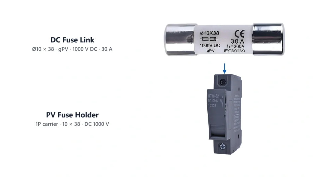
DC fuse keeps blowing troubleshooting with photovoltaic fuse and holderWhy Does a DC Fuse Keeps Blowing?
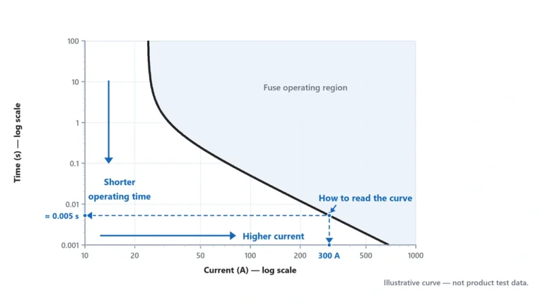
A fuse opens when its element reaches the thermal conditions required by its time-current characteristic.
A higher current generally causes faster operation, but a fuse does not necessarily open immediately when current slightly exceeds its nominal rating.
For example, a 20 A fuse should not be assumed to blow as soon as circuit current reaches 20.1 A.
Actual opening time depends on:
- magnitude and duration of overcurrent;
- fuse construction and operating characteristic;
- ambient temperature;
- previous thermal loading;
- the manufacturer’s time-current data.
A blown fuse therefore tells you that the element has opened, but it does not identify the underlying cause.
The fault may be electrical, thermal or related to component selection.
First Identify the Failure Pattern
Before starting the technical investigation, collect basic information about when the fuse operates.
| Failure Pattern | Possible Causes |
|---|---|
| Blows immediately when equipment is energized | Short circuit, severe fault, incorrect connection or incompatible fuse characteristic |
| Blows after operating for some time | Sustained overload, thermal derating or unsuitable fuse selection |
| Blows during high solar production | Elevated current, reverse-current conditions or excessive combiner temperature |
| Problem appears after rain or moisture | Insulation damage, water ingress or intermittent ground fault |
| One PV string repeatedly loses its fuse | String-specific wiring fault, reverse current or defective equipment |
| Holder becomes discolored or melted | Contact resistance, poor termination or excessive thermal loading |
| Inverter displays a fuse-related fault | Possible external fuse failure, internal protective device or monitoring fault |
These patterns are diagnostic clues, not definitive proof of any particular failure.
7 Common Causes of a Blown DC Fuse
1. Short Circuit in the DC Wiring
A short circuit occurs when conductors become connected through an unintended low-impedance path.
Potential causes include:
- damaged cable insulation;
- crushed or pinched wiring;
- incorrect terminal connections;
- conductive contamination;
- damaged equipment;
- incorrectly assembled connectors.
A sufficiently severe short circuit can cause rapid fuse operation.
In a photovoltaic installation, the available fault current also depends on the PV array configuration and other connected sources.
A single current-limited PV string may not produce enough fault current to operate every type of fuse rapidly.
A short circuit is not guaranteed to produce an immediate blown fuse in every PV architecture.
2. Reverse Current From Parallel PV Strings
Reverse current is one of the most important reasons for using string fuses in multi-string photovoltaic arrays.
Consider four identical strings connected in parallel.
Under normal operation, they supply current toward the inverter.
If one string develops a fault, the remaining strings may supply current backward into the faulted string.
The affected circuit can therefore receive current from other strings in addition to any current it generates itself.
A correctly selected gPV fuse can interrupt excessive reverse current when the applicable operating conditions are met.
However, repeated operation of one string fuse should not automatically be attributed to reverse current. The fault path and current contribution must be investigated.
For a detailed explanation of when parallel PV strings require protection, see our Solar Panel Fuse Guide.

Solar PV blown fuse caused by reverse current from parallel strings3. Ground Fault or Insulation Failure
Photovoltaic systems are exposed to environmental conditions that can gradually damage insulation.
Common causes include:
- damaged cable jackets;
- moisture inside connectors;
- water ingress into an enclosure;
- conductors rubbing against metal structures;
- pinched cables;
- deteriorated module insulation.
Ground faults can be permanent or intermittent.
For example, a system may show faults only after rain, when moisture changes the insulation resistance of an already damaged circuit.
Fluke explains how ground faults in photovoltaic systems can be associated with damaged wiring, moisture and installation-related problems.
Important: A ground fault does not necessarily blow a string fuse. It may instead trigger inverter ground-fault protection, or remain undetected by an ordinary fuse.
A fuse-related failure should therefore be diagnosed separately from an inverter insulation or ground-fault alarm.
4. Incorrect Fuse Current Rating
An undersized fuse may operate during normal circuit conditions.
However, fuse sizing involves more than checking the module current.
For photovoltaic protection, the selected fuse must coordinate with:
- module short-circuit current (Isc);
- applicable maximum circuit-current calculation;
- maximum series fuse rating;
- conductor ampacity;
- fuse-holder ratings;
- ambient temperature;
- required protection characteristic.
A commonly used conventional NEC-based PV source-circuit calculation is:
Minimum OCPD rating ≈ 1.56 × Isc
This method is not universal for all DC circuits and does not independently establish the correct fuse rating.
If the calculated fuse rating appears unsuitable, the correct response is to reassess the complete protection design.
Do not simply install a larger fuse.
See our Solar Fuse Sizing Guide for the current-rating calculation and its limitations.
5. Excessive Ambient Temperature
Fuses are thermal devices.
Elevated ambient temperature can affect how much continuous current a fuse can carry without opening.
This matters especially inside solar combiner boxes, where temperature may rise because of:
- direct sunlight on the enclosure;
- limited ventilation;
- multiple adjacent fuse holders;
- fuse power dissipation;
- surrounding protective equipment;
- continuous operating current.
The relevant temperature is the temperature surrounding the installed fuse, not merely the outdoor weather temperature.
Eaton’s Fuse Technical FAQs explain that ambient temperature affects fuse current-carrying and operating characteristics and that manufacturers provide appropriate derating curves.
A fuse selected without considering the actual enclosure temperature may operate earlier than expected.
Before changing the rating, check the manufacturer’s temperature data and whether the holder, cable and protected equipment permit the proposed alternative.
6. Loose Contacts or an Incompatible Fuse Holder
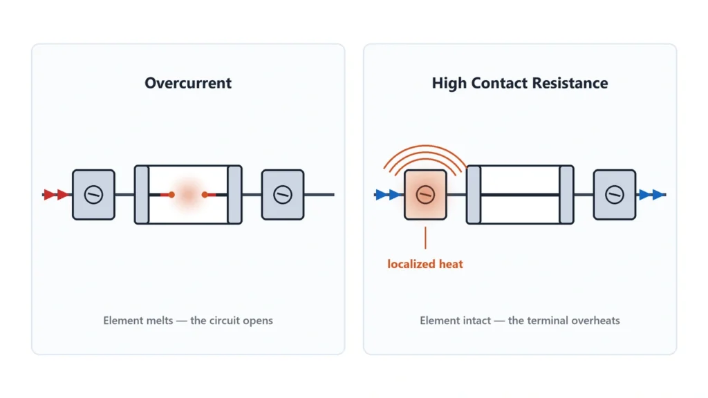
A fuse holder that becomes unusually hot may indicate a connection problem rather than a true overcurrent fault.
Possible causes include:
- inadequate contact pressure;
- incorrect fuse dimensions;
- worn or damaged contacts;
- corrosion;
- loose terminals;
- unsuitable conductor termination;
- excessive fuse power loss.
The underlying relationship is:
P = I²R
As contact resistance increases, more heat is produced at the connection for a given current.
This can create a damaging cycle:
Higher Resistance → More Heat → Contact Degradation → Resistance Increases
A poor connection can damage the fuse holder even when the fuse element has not operated.
This distinction matters:
A melted fuse holder is not proof that the fuse successfully interrupted an overcurrent.
The fuse may still have continuity while its terminals or holder have suffered serious thermal damage.
Where thermal damage is present, the affected holder and connections must be evaluated rather than merely installing a replacement fuse.
See DC Fuse Disconnector vs Fuse Holder for the functions and compatibility requirements of fuse mounting devices.
DC fuse holder overheating caused by high contact resistance7. Incorrect Fuse Type or System Configuration
Not all DC-rated fuses are suitable for photovoltaic protection.
A fuse may have the correct physical dimensions and current rating but an unsuitable operating characteristic.
For example:
20 A general DC fuse ≠ automatically 20 A gPV fuse
PV applications can require fuse-links specifically designed for sustained DC voltage and the relatively low fault currents possible in photovoltaic arrays.
Other configuration problems may include:
- incorrect fuse location;
- unexpected backfeed from another source;
- inappropriate fuse utilization category;
- incorrectly coordinated upstream and downstream protection;
- unsuitable inverter or combiner integration.
For a PV string, verify that the fuse type is appropriate for the application.
See our gPV Fuse Guide for the relevant photovoltaic fuse category.
How to Tell Whether a DC Fuse Is Blown
Not all fuse failures are visually obvious.
Some cartridge fuses have opaque ceramic bodies that prevent direct inspection of the internal element.
Even with transparent fuse bodies, visual inspection alone may not confirm the electrical condition.
Signs of a Possible Blown Fuse
Common symptoms include:
- one PV string stops contributing current;
- a combiner monitoring system reports an open fuse;
- an inverter reports an external protection fault;
- a fuse indicator changes state;
- the circuit loses continuity;
- the fuse element is visibly open, where inspection is possible.
However, these symptoms can also have other explanations.
For example, a PV string that produces no current may be affected by an open connector, broken conductor, inverter operating condition or another circuit fault.
Blown Fuse vs Overheated Holder
| Observation | What It May Indicate |
|---|---|
| Fuse has no continuity when safely isolated | Open fuse element |
| Fuse has continuity but circuit does not operate | Fault elsewhere in the circuit or connections |
| One fuse contact is unusually hot | Possible localized contact resistance |
| Holder is discolored or melted | Thermal damage requiring further investigation |
| Fuse repeatedly opens after replacement | Unresolved fault or unsuitable protection specification |
| Inverter reports a protection fault | Requires correlation with actual fuse and circuit condition |
A continuity test is useful for confirming whether the fuse element is open.
A continuity result alone does not establish that the fuse is suitable for reuse in a damaged or overheated assembly.
How to Test a DC Fuse With a Multimeter
A multimeter can be used to test a fuse for continuity, but testing a high-voltage DC fuse is not equivalent to checking a small automotive blade fuse.
Solar PV strings can remain energized in daylight even when the inverter is switched off. Parallel strings, batteries and other sources may also create unexpected backfeed.
High-voltage DC inspection and isolation should be performed by qualified electrical personnel using appropriate procedures and equipment.
Safe Testing Principles
Before an off-circuit fuse continuity test:
- Identify all possible electrical sources, including backfeed paths.
- Follow the equipment manufacturer’s shutdown and isolation procedure.
- Apply the required lockout/tagout controls.
- Verify absence of voltage using appropriately rated test equipment and an approved test method.
- Remove the fuse only after the relevant circuit has been safely isolated and verified.
- Test the isolated fuse with the multimeter in continuity or resistance mode.
Never use continuity or resistance mode on an energized circuit.
Fluke’s How to Check a Fuse With a Multimeter explains the basic off-circuit continuity test.
Understanding the Multimeter Reading
| Multimeter Result | Typical Interpretation |
|---|---|
| Continuity tone and low resistance | Fuse element is likely continuous |
| OL / open circuit / no continuity | Fuse element is open |
| Unstable or unexpected result | Check test contact, meter configuration and fuse specifications |
A good continuity result confirms only that an electrical path exists through the fuse at the meter’s test conditions.
It does not independently verify breaking capacity, rated current or the fuse’s condition under load.
When Professional Testing Is Required
Some faults cannot be identified through fuse continuity alone.
A qualified technician may need to evaluate:
- PV string current;
- insulation resistance;
- terminal contact condition;
- fault history and monitoring records;
- inverter diagnostic information;
- thermal condition under permitted operating tests.
Any energized testing requires the appropriate risk assessment, qualifications, PPE and suitably rated instruments.
A fuse holder that is not specifically load-break rated must not be opened under load.
Why a Solar Combiner Box Fuse Keeps Failing
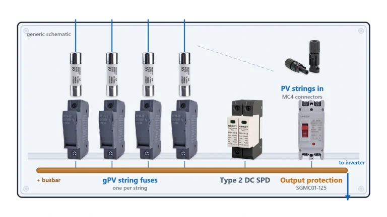
If a fuse repeatedly operates inside a PV combiner box, identify whether the problem is limited to one input or affects several circuits.
One String Fuse Repeatedly Fails
Investigate:
- the affected PV string and wiring;
- possible reverse-current sources;
- insulation defects;
- module maximum series fuse rating;
- fuse and holder compatibility;
- localized temperature abnormalities.
Multiple String Fuses Fail
Investigate the wider system configuration, including:
- combiner busbar and terminal arrangement;
- common wiring faults;
- abnormal connected sources;
- system protection coordination;
- enclosure operating temperature.
Output Protection Operates
The output circuit carries combined current from the connected parallel strings.
Its protection requirements differ from those of an individual string.
Do not replace an output fuse based on the ampere rating of one string.
See our PV Fuse Box Guide for the distinction between individual string fuses and combined-output protection.
When the Fuse Is Not the Root Cause
A fuse may be operating correctly because it is responding to a real fault.
The objective of troubleshooting is not merely to stop the fuse from opening.
It is to determine whether the fuse is:
Protecting the circuit correctly
or:
Operating because the protection design is unsuitable
or:
Being affected by a thermal or installation defect.
DC Fuse Troubleshooting Checklist and Replacement
The following checklist summarizes the information an electrical technician or OEM service team should collect.
| Check | Information Required |
|---|---|
| Fuse condition | Confirm whether the element is open |
| Failure timing | Immediate, delayed, intermittent or weather-related |
| Circuit type | PV string, combined PV output, battery or other DC circuit |
| Maximum voltage | Calculated DC voltage and fuse rating |
| Current | Normal current and applicable protection limits |
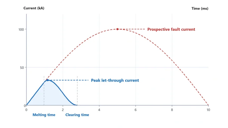
| Fault current | Prospective current and fuse breaking capacity |
| Fuse class | gPV or other suitable application category |
| Holder condition | Contacts, terminals, discoloration and mechanical damage |
| Temperature | Expected operating and enclosure temperatures |
| Connected sources | Parallel strings, battery, inverter or other backfeed |
| Previous failures | Repeated operation in the same circuit or multiple circuits |
Can You Replace a Blown DC Fuse With a Higher-Amp Fuse?
Do not increase the fuse current rating merely to prevent repeated operation.
An oversized protective device may no longer provide the protection required for the conductor or connected equipment.
A replacement must be selected according to the complete protection specification.
Can You Replace Only the Fuse After the Holder Melts?
Not without evaluating the damaged holder and connections.
Heat-damaged insulation, weakened contacts or degraded terminals can remain unsafe even after a new fuse is installed.
The source of overheating must be corrected before the circuit is returned to service.
What Should the Replacement Fuse Match?
Check at least:
- fuse utilization category;
- rated current and operating characteristic;
- rated DC voltage;
- breaking capacity;
- physical dimensions;
- holder compatibility;
- applicable certification or project requirements.
Where a manufacturer specifies an exact replacement part, follow that documentation.
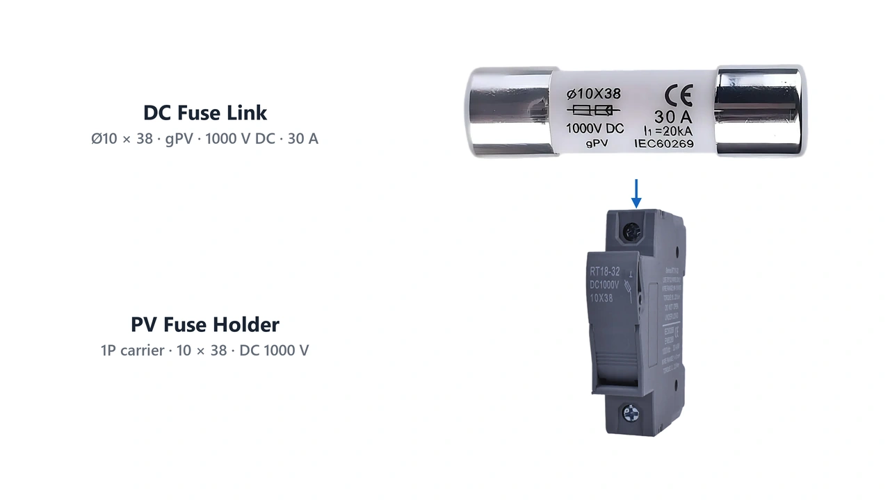
For photovoltaic applications, available fuse-link and holder configurations can be reviewed in UHCCY’s DC Fuse range.
For complete array protection equipment, see our PV Combiner Box family.
Final Troubleshooting Principle
A repeated blown fuse should be investigated in this order:
Confirm Failure → Identify Fault Sources → Check Circuit Ratings → Inspect Holder and Connections → Correct Root Cause → Verify Replacement → Return to Service
A fuse should never be bypassed, bridged with wire or replaced by a higher current rating simply to restore operation.
For a DC or solar PV project, correct troubleshooting means restoring the intended protection—not just restoring current flow.