Table of Contents
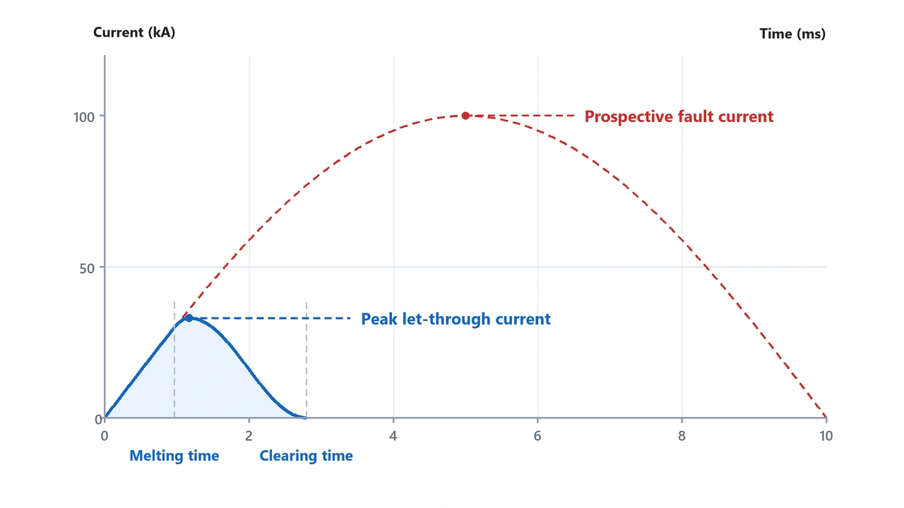
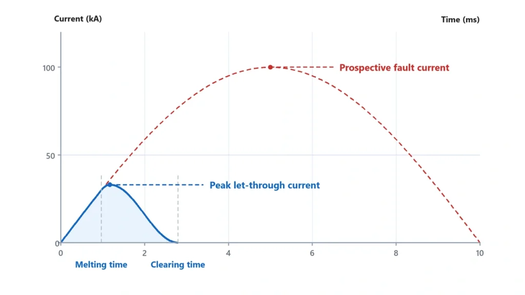
A current limiting fuse is designed to interrupt a sufficiently high fault before the prospective fault current reaches the peak value it would otherwise achieve. By reducing both peak let-through current and fault duration, the fuse can significantly reduce the thermal and mechanical stress imposed on cables, busbars, terminals and connected equipment.
This function is related to—but different from—breaking capacity.
A fuse can have a high breaking capacity because it can safely interrupt a large prospective fault current. Current limitation describes how much of that fault current and fault energy actually passes through the circuit before interruption is completed.
Terms such as HRC fuse, interrupting rating, peak let-through current and I²t therefore describe different aspects of fuse performance and should not be used interchangeably.
For the broader principles of voltage, current and DC fuse selection, see our DC Fuse Guide.
What Is a Current Limiting Fuse?
A current limiting fuse interrupts a severe fault quickly enough to prevent the prospective fault current from reaching its unrestricted peak.
Without effective current limitation:
Fault occurs → current rises → prospective peak current → protection interrupts
With an effective current-limiting fuse:
Fault occurs → fuse element melts → arc develops inside fuse → fuse impedance rises → current peaks at a lower value → fault clears
The current that actually passes through the fuse is called let-through current.
Mersen’s technical guidance defines let-through current as the current passed by the fuse while it is interrupting a fault within its current-limiting range and identifies peak let-through current (Ip) and I²t as two important measures of current limitation.
Mersen — Current Limiting and Let-Through Energy
Why Current Limitation Matters
Fault current produces both thermal and mechanical stress.
Thermal effects increase approximately with:
I² × time
while electromagnetic forces also increase strongly as fault current rises.
Reducing the current peak and clearing time can therefore reduce stress on:
- conductors;
- busbars;
- terminals;
- contactors;
- semiconductor devices;
- enclosure components;
- downstream equipment.
This does not mean every fuse limits every overcurrent.
Current limitation becomes significant when the fault is sufficiently high for the fuse to enter its current-limiting operating region.
A modest overload may take considerably longer to clear and may not produce meaningful peak-current limitation.
Current limiting fuse reducing peak let-through fault currentBreaking Capacity vs Current Limiting: What Is the Difference?
These two characteristics are related but they answer different engineering questions.
Breaking Capacity
Breaking capacity describes how much prospective fault current the fuse can safely interrupt under specified conditions.
For example, a fuse might have:
Rated current: 20 A
but a breaking capacity measured in:
kA
The 20 A value describes the fuse’s nominal current rating.
The breaking capacity describes the maximum fault-current environment in which the fuse has been designed and tested to interrupt safely.
The current IEC 60269-1:2024 applies to enclosed current-limiting fuse-links with rated breaking capacities of at least 6 kA, for circuits up to 1000 V AC or 1500 V DC.
That is the scope of the standard—not a statement that every fuse has exactly 6 kA breaking capacity.
Individual products can have substantially different ratings.
Current Limitation
Current limitation asks a different question:
How much current actually passes through the circuit before the fault is cleared?
Suppose the prospective fault current is:
50 kA
A correctly rated fuse may be capable of safely interrupting that fault.
But if it is also strongly current-limiting, the actual instantaneous peak that passes through downstream equipment may be far below the unrestricted prospective peak.
Therefore:
Breaking capacity = Can the fuse safely interrupt the available fault?
Current limitation = How much peak current and energy passes through before it clears?
Interrupting Rating
The term interrupting rating is widely used, particularly in North American terminology.
In practical selection discussions it serves a similar purpose to breaking capacity: defining the fault-current level the protective device can safely interrupt under its specified conditions.
However, always use the exact terminology and test basis stated in the manufacturer’s datasheet and applicable standard.
Do not compare two kA values without confirming that they refer to equivalent ratings and test conditions.
What Is an HRC Fuse?
HRC stands for:
High Rupturing Capacity
The term is commonly associated with industrial fuse-links designed to safely interrupt high prospective fault currents.
Eaton uses the term HRC for High Rupturing Capacity fuse-links and associates it with current-limiting low-voltage fuse systems such as NH fuse-links.
Eaton — Low-Voltage Fuse Application Guide
However, HRC should not be treated as a complete modern fuse specification.
A procurement request such as:
Need 20 A HRC fuse.
is incomplete.
You still need to know:
- AC or DC;
- voltage rating;
- utilization category;
- breaking capacity;
- dimensions;
- time-current characteristic;
- application;
- required certification.
HRC Does Not Mean gPV
This distinction is especially important for solar systems.
A fuse may be described broadly as an HRC or high-breaking-capacity fuse without being a photovoltaic gPV fuse.
For PV string protection, the applicable fuse characteristics must be verified for the photovoltaic application.
See our gPV Fuse Guide for the difference.
HRC Does Not Mean “Any Ceramic Fuse”
Many high-breaking-capacity fuses use:
- ceramic bodies;
- metallic fuse elements;
- arc-quenching filler.
But physical construction alone does not establish the fuse rating.
A ceramic cartridge should not automatically be called an HRC fuse merely because it contains silica filler or looks similar to an industrial fuse.
Always use the manufacturer’s documented ratings.
Peak Let-Through Current and I²t Explained
Two of the most useful ways to describe current-limiting fuse performance are:
Peak Let-Through Current (Ip)
and:
I²t
They describe related but different effects.
Peak Let-Through Current
Peak let-through current is the highest instantaneous current that passes through the fuse while it is clearing a current-limiting fault.
Suppose an electrical system has a very high prospective short-circuit current.
Without current limitation:
Prospective peak = very high
With the fuse:
Actual peak = lower
The difference represents the fuse’s peak-current-limiting effect.
This matters because high instantaneous current can produce strong electromagnetic forces on:
- busbars;
- conductors;
- terminals;
- contacts;
- equipment structures.
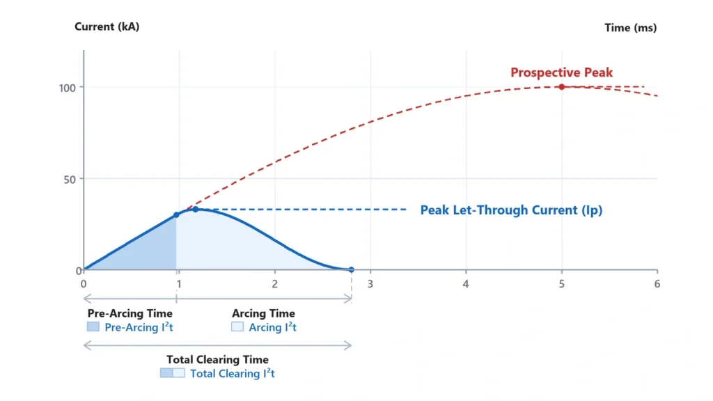
What Is I²t?
I²t represents the integral of current squared over time:
I²t = ∫ i² dt
It is commonly used as an indication of the thermal energy associated with the fuse operating process.
Because current is squared, large fault currents have a particularly strong effect on the resulting value.
Fuse documentation may distinguish between:
Pre-Arcing I²t
The energy passed before the fuse element melts and arcing begins.
Also commonly called:
melting I²t
Total Clearing I²t
The total energy passed from fault initiation until the fuse completely interrupts the circuit.
This includes:
pre-arcing period + arcing period
For protection coordination, total clearing I²t can be particularly important because downstream equipment experiences the complete fault-clearing event.
Lower I²t Is Not Automatically “Better”
A lower I²t can provide stronger energy limitation for sensitive equipment.
But fuse selection cannot be reduced to:
lowest I²t = best fuse
The fuse still has to satisfy:
- normal load current;
- inrush conditions;
- system voltage;
- fault current;
- equipment coordination;
- fuse class;
- application requirements.
An excessively fast fuse can create nuisance operation in an application requiring temporary overload or inrush capability.
Current limiting fuse I2t and peak let-through current explainedHow to Read Fuse Curves and Let-Through Charts
Fuse manufacturers typically provide more than one type of performance graph.
Two should not be confused:
Time-current curve
and:
peak let-through curve
Time-Current Curve
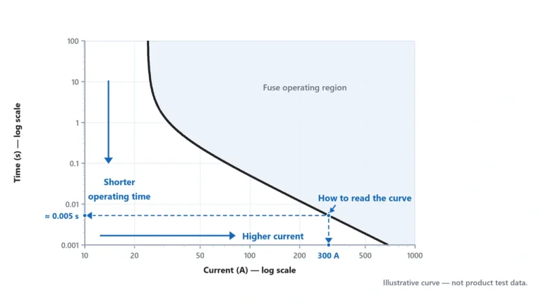
A time-current curve answers:
How long will this fuse take to operate at a particular current?
The horizontal axis usually represents current.
The vertical axis represents time.
As current rises, operating time generally decreases.
For example:
small overload
→ relatively long operating time
large fault
→ very short operating time
This curve is useful for:
- overload protection;
- fuse coordination;
- avoiding nuisance operation;
- comparing operating characteristics.
It does not directly tell you the actual peak fault current that passes through during a severe current-limiting event.
Peak Let-Through Curve
A peak let-through chart answers:
If the available fault current is this high, what maximum instantaneous current will the fuse allow through?
The chart normally compares:
prospective RMS fault current
with:
peak instantaneous let-through current
This is useful when evaluating mechanical and electrical stress on downstream equipment.
I²t Data
Manufacturers may provide I²t as:
- tables;
- curves;
- minimum values;
- maximum values;
- pre-arcing values;
- total clearing values.
Always verify exactly which I²t value is being quoted.
Mersen specifically notes that published fuse I²t values are often based on AC test conditions unless otherwise stated, and that DC I²t can vary with factors including voltage, available fault current and DC circuit time constant.
That point is particularly important for UHCCY applications:
Do not take an AC I²t value and automatically present it as the DC performance of a PV fuse.
Use the manufacturer’s actual DC data when DC coordination depends on I²t.
What Current Limiting Means in DC and Solar PV Systems
The current-limiting concept also applies to DC protection, but the application must be evaluated using DC-specific product data.
DC faults differ from AC faults because steady DC does not provide natural periodic current-zero crossings.
The fuse must interrupt the fault through its own internal arc-control process.
For the AC/DC interruption difference, see AC Fuse vs DC Fuse.
PV String Circuits
PV strings have an unusual characteristic:
fault current can be relatively low compared with conventional industrial power systems
because PV modules are current-limited energy sources.
The main problem in parallel arrays may instead be reverse current from healthy strings into a faulted string.
For that reason, photovoltaic protection is not simply about finding the fuse with the highest breaking capacity.
The fuse also needs an operating characteristic suited to PV fault currents.
That is one reason gPV fuse-links are used for photovoltaic string protection.
PV Combiner Boxes
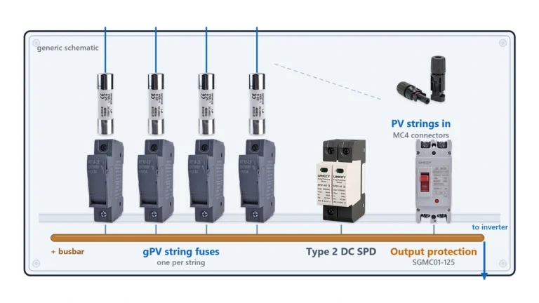
A typical architecture may be:
PV String
→ gPV Fuse
→ Fuse Holder
→ Busbar
→ Combined Output Protection
The string fuse needs to coordinate with:
- module maximum series fuse rating;
- string conductor;
- fuse holder;
- available reverse current;
- ambient temperature.
The combined output circuit has different fault-current conditions and therefore requires its own protection assessment.
Batteries and Other DC Sources
Battery systems can have very different fault characteristics from PV strings.
A battery may be capable of delivering extremely high short-circuit current.
A fuse suitable for a solar string should therefore not automatically be assumed suitable for a battery circuit simply because:
voltage matches
and:
ampere rating matches
Breaking capacity and the actual DC interruption characteristics become particularly important.
How Breaking Capacity Relates to Fuse vs Circuit Breaker Selection
Fuses and circuit breakers can both interrupt short-circuit current.
However, their current-limiting behavior can differ substantially.
A current-limiting fuse can begin interrupting a severe fault before the first unrestricted current peak is reached.
Certain circuit breakers can also provide current limitation, so it would be incorrect to say:
Fuses are current limiting; breakers are not.
The actual comparison depends on the products being evaluated.
A more useful comparison is:
Fuse peak let-through curve
versus:
Breaker let-through / current-limiting data
under the same prospective fault conditions.
For a broader comparison of the two protection technologies, see our Fuse vs Circuit Breaker.
Breaking Capacity Does Not Replace Coordination
Suppose:
Available fault current = 20 kA
Fuse breaking capacity = 50 kA
The fuse may have sufficient interruption capacity.
But that does not by itself prove that:
- the conductor is adequately protected;
- downstream equipment can withstand the let-through energy;
- upstream/downstream selectivity is correct;
- the fuse has the right current rating;
- the fuse is suitable for the application.
Breaking capacity answers one critical question.
It does not answer every protection question.
Selecting a Current Limiting Fuse for a DC Project
For an engineering specification or B2B RFQ, avoid requesting only:
High breaking capacity fuse
or:
HRC fuse
Those descriptions leave too many variables undefined.
A useful specification should include:
Application
→ PV / battery / DC distribution / industrial equipment
Current type
→ DC
Maximum circuit voltage
Rated current
Prospective fault current
Required breaking capacity
Fuse utilization category
→ gPV / other applicable category
Time-current requirement
Peak let-through / I²t requirement
→ where equipment coordination requires it
Fuse dimensions
Holder or fuse-base requirement
Ambient temperature
Applicable IEC / UL requirement
The resulting specification may therefore look like:
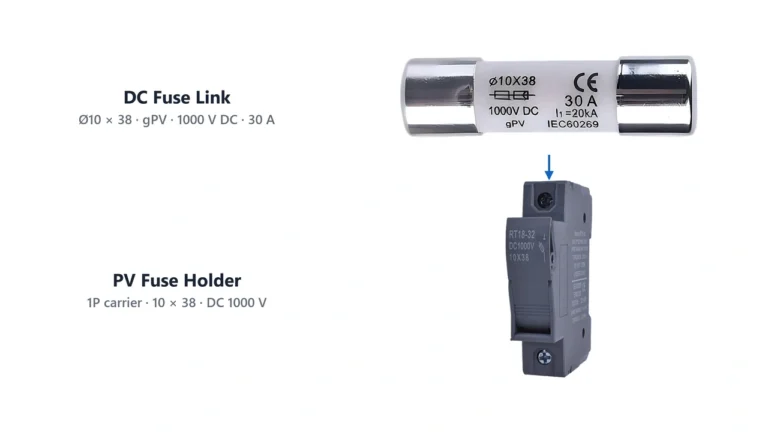
20 A / 1000 V DC / gPV / specified breaking capacity / 10 × 38 mm
rather than:
20 A HRC fuse
For photovoltaic current calculation, see the Solar Fuse Sizing Guide.
For available UHCCY photovoltaic fuse-links and compatible fuse holders, see the DC Fuse range.
The core selection logic is:
Rated current tells you how the fuse carries and responds to current.
Voltage rating tells you the DC voltage it can interrupt.
Breaking capacity tells you the maximum prospective fault it can safely clear.
Peak let-through current tells you how much instantaneous current passes during a current-limiting event.
I²t tells you how much current-squared-time energy passes through during operation.
These parameters work together. None should be substituted for another when specifying protection for a DC system.