Table of Contents
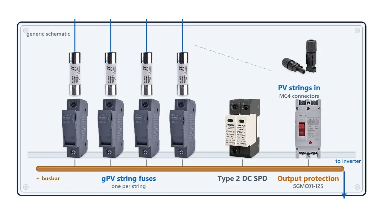
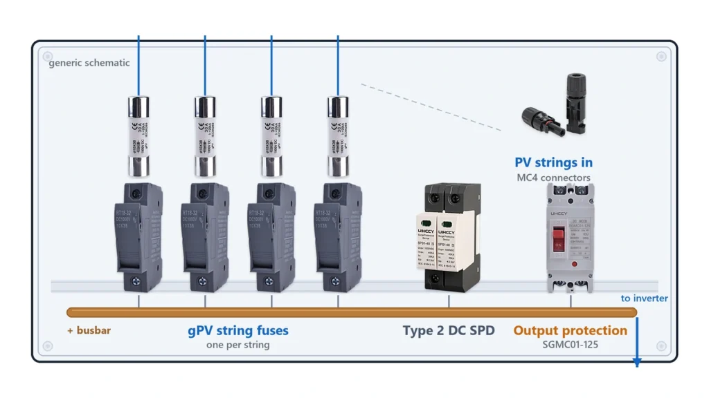
A PV fuse box—more commonly called a photovoltaic combiner box when it combines multiple PV strings—provides an organized location for string overcurrent protection before several solar circuits are connected to a common DC output.
The fuse arrangement inside the box must do more than match the current printed on the PV module. Correct design requires coordination between the PV string, gPV fuse, fuse holder, busbar, output conductor and inverter input.
In a typical multi-string system:
PV Strings → Individual String Fuses → Common Busbar → Combined DC Output → Inverter
The individual string fuses primarily protect against excessive reverse current from other parallel strings. Depending on the system architecture, the combined output circuit may require additional protection as well.
This guide explains where the fuses belong, how their ratings are calculated, when output protection is required and how the internal components of a solar combiner box should be coordinated.
For the fundamentals of DC fuse current, voltage and breaking capacity, start with our DC Fuse Guide.
What Is a PV Fuse Box?
A PV fuse box is a DC protection assembly containing one or more photovoltaic fuse circuits.
In solar installations, the term often refers to a PV combiner box equipped with individual string fuses.
Its basic purpose is:
multiple PV strings → individual protection → common combined output
A typical internal architecture may contain:
- gPV fuse-links;
- fuse holders;
- input terminals;
- copper busbars;
- DC surge protective devices;
- output circuit breaker or disconnecting device where required;
- output terminals;
- enclosure and cable glands.
Not every combiner box contains exactly the same components.
For example, one project may use:
4 strings → 4 fuse circuits → SPD → output breaker → 1 output
while another may use:
2 strings → protection devices → 2 independent outputs
The correct configuration depends on the electrical architecture rather than a universal combiner-box layout.
UHCCY supplies project-specific configurations through the PV Combiner Box product family.
PV Fuse Box vs Ordinary DC Fuse Box
A generic DC fuse box is not automatically suitable for photovoltaic strings.
PV systems can operate at:
- high continuous DC voltage;
- relatively low but sustained fault currents;
- outdoor temperatures;
- parallel-source reverse currents;
- 1000 V or 1500 V system architectures.
Photovoltaic fuse-links are therefore normally selected with gPV characteristics where applicable.
IEC 60269-6 specifies supplementary requirements for fuse-links protecting PV strings and arrays in circuits up to 1500 V DC.
For more detail on that fuse category, see our gPV Fuse Guide.
PV fuse box with string fuses inside a solar combiner boxWhere Should Fuses Be Installed in a PV Combiner Box?
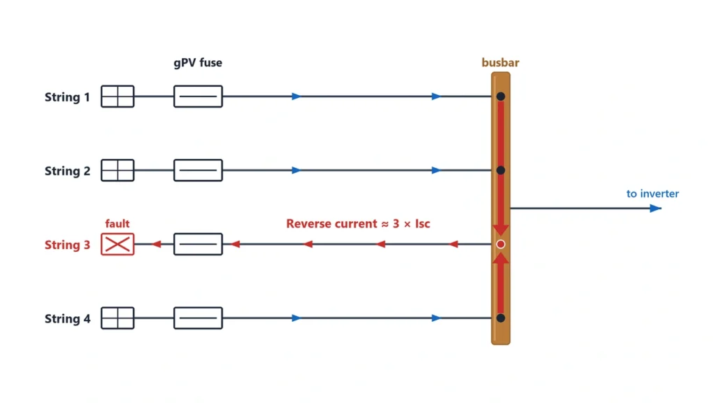
The most important rule is that a string fuse must be positioned so it can isolate excessive current entering the protected string.
In a conventional parallel-string combiner:
String 1 → Fuse 1 →
String 2 → Fuse 2 → Common Busbar → Output
String 3 → Fuse 3 →
String 4 → Fuse 4 →
The fuses are placed before the individual string conductors join the common busbar.
This arrangement allows each string to be protected independently.
Why the Fuse Must Be Before the Parallel Connection
Assume four strings are connected in parallel and String 1 develops a fault.
Strings 2, 3 and 4 can potentially feed current backward through the common busbar toward String 1.
If Fuse 1 is correctly positioned in series with the String 1 conductor:
Healthy Strings → Busbar → Fuse 1 → Fault
Fuse 1 can interrupt the excessive reverse current.
If several strings are permanently paralleled before reaching a single common fuse, that fuse cannot provide the same individual string protection.
The distinction is therefore:
One fuse per protected string circuit
rather than:
one fuse somewhere after everything has already been combined
Whether an individual string actually requires overcurrent protection depends on the available reverse current, conductor ampacity, module maximum series-fuse rating and applicable electrical requirements.
That decision is covered in detail in our Solar Panel Fuse Guide.
A Combiner Box Does Not Automatically Require One Fuse Per String
Do not reverse the logic.
A combiner box having four inputs does not itself prove that four fuses are required.
The protection requirement must still be established from the system design.
Some architectures may use:
- electronically controlled inputs;
- integrated protection elsewhere;
- configurations where available reverse current does not exceed the permitted limits.
IEC 62548-1:2023+A1:2025 covers current international PV array design requirements, including DC array wiring, electrical protection and switching provisions.
For U.S. installations, the applicable edition of NFPA 70, National Electrical Code should also be checked. The current NEC edition is 2026, although the edition legally adopted in a particular jurisdiction may differ.
PV fuse box string fuse placement before the combiner busbarHow to Size PV String Fuses in a Combiner Box
The combiner box does not change the fundamental string-fuse calculation.
Each individual string fuse is selected primarily from the electrical characteristics of that string and the equipment it protects.
Important inputs include:
- module Isc;
- module maximum series fuse rating;
- maximum string voltage;
- modules per string;
- number of parallel strings;
- string conductor ampacity;
- ambient temperature;
- fuse-holder rating.
Example String Data
Assume each PV string uses modules with:
| Parameter | Example Value |
|---|---|
| Module Isc | 12.5 A |
| Module Voc | 49 V |
| Maximum Series Fuse Rating | 25 A |
| Parallel Strings | 4 |
These values are illustrative only.
Conventional NEC-Based Fuse Calculation
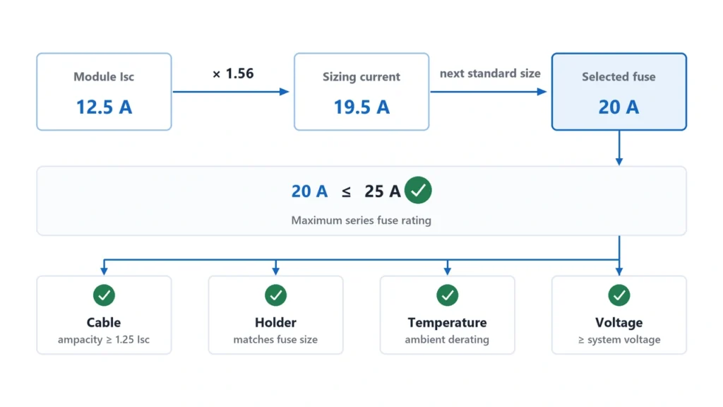
For a conventional NEC-based PV source-circuit calculation, a commonly used starting point is:
Minimum fuse rating ≈ 1.56 × Isc
Using the example:
1.56 × 12.5 A = 19.5 A
A possible next standard fuse rating could therefore be:
20 A
provided all other limits permit that selection.
The selected fuse must then satisfy:
20 A ≤ module maximum series fuse rating
In this example:
20 A ≤ 25 A
so the module limit is not exceeded.
The conductor and fuse holder must also safely support the selected rating under the actual thermal conditions.
Littelfuse provides the same conventional NEC-based sizing methodology in its Photovoltaic Fuse Sizing Guide.
For the complete calculation process, including temperature and voltage checks, see our Solar Fuse Sizing Guide.
Do Not Multiply the String Fuse Rating by the Number of Strings
This is a common error.
Four strings using 20 A string fuses does not mean each fuse should be:
20 A × 4 = 80 A
Each string fuse protects its individual string.
Therefore:
String fuse → based on individual string current
The combined output circuit is calculated separately.
Check the Module Maximum Series Fuse Rating
The module manufacturer’s maximum series fuse rating remains an upper limit.
If the calculated minimum fuse current exceeds the module’s permitted maximum OCPD, the correct response is not to install an oversized fuse.
The system design needs to be reassessed.
Check Fuse Voltage Independently
A 20 A calculation determines current class.
It does not determine whether the fuse should be:
1000 V DC
or:
1500 V DC
Maximum cold-weather string Voc must be calculated separately.
See 1000V Solar Fuse vs 1500V for the voltage-selection process.
PV fuse box string fuse sizing calculationHow to Size the Combiner Box Output Protection
After individual strings are combined, the output conductor carries the sum of the parallel string currents.
This creates a different circuit from each individual PV string.
Using the previous example:
4 strings × 12.5 A Isc = 50 A combined Isc
A conventional NEC-based preliminary OCPD calculation could therefore begin with:
1.56 × combined Isc
or:
1.56 × 50 A = 78 A
This calculation illustrates the difference between:
individual string fuse ≈ 20 A
and:
combined output current basis ≈ 78 A minimum OCPD calculation
However, this does not mean every four-string combiner should automatically use an 80 A fuse or breaker.
Does Every Combiner Box Need an Output Fuse?
No.
Output overcurrent protection depends on the complete system architecture.
You need to consider:
- output conductor ampacity;
- downstream inverter input;
- whether another source can backfeed the circuit;
- equipment ratings;
- upstream/downstream protection;
- applicable electrical code;
- whether the output protective device also provides switching or isolation.
PV modules themselves are current-limited sources.
If no other source can supply damaging overcurrent into the output circuit, the protection requirement can differ from a conventional distribution circuit.
Therefore:
String fuses and output protection solve different problems.
Do not automatically duplicate one with the other.
Fuse or Circuit Breaker at the Combiner Output?
Either may be appropriate depending on the system design.
A fuse can offer:
- compact protection;
- strong current-limiting performance;
- high interrupting capability depending on design.
A DC circuit breaker can provide:
- resettable protection;
- manual operation;
- possible isolation or switching functions depending on rating.
These devices are not interchangeable solely because their ampere ratings match.
See Fuse vs Circuit Breaker for the detailed comparison.
Output Busbar Rating
The busbar must also carry the combined current.
For example:
4 × 12.5 A Isc
does not become a 12.5 A busbar circuit after the strings are combined.
The busbar, output terminals and conductor must all be selected for the combined circuit current under applicable design margins and thermal conditions.
This is especially important in compact boxes where heat from:
- fuses;
- fuse holders;
- SPD;
- breaker;
- terminals;
is concentrated inside one enclosure.
Positive, Negative, One-Pole or Two-Pole Fusing?
Another common PV fuse box question is:
Should I fuse only the positive conductor or both positive and negative conductors?
There is no universal answer based purely on system voltage.
The correct arrangement depends on:
- grounding configuration;
- array architecture;
- inverter topology;
- ground-fault protection;
- local electrical requirements;
- equipment instructions.
One-Pole String Protection
Some system architectures permit a single overcurrent protective device in one conductor of the string.
The same polarity should then normally be used consistently across equivalent circuits where required by the applicable code.
Two-Pole String Protection
Other systems use protection in both positive and negative conductors.
This may be associated with ungrounded or floating DC arrays, project specifications or particular protection architectures.
However:
2P holder ≠ automatically required for every PV string
and:
1P holder ≠ automatically correct for every system
The system grounding and applicable standard must be checked.
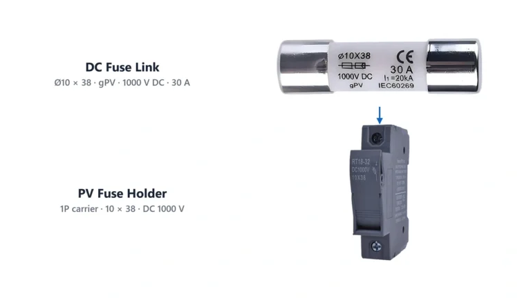
UHCCY currently provides both single- and multi-pole photovoltaic fuse-holder configurations within the DC Fuse family, depending on the fuse platform and application.
Do Not Use Pole Count to Increase Voltage Unless Specified
Another important distinction:
Two poles should not be connected in series to obtain a higher fuse-holder voltage unless the manufacturer specifically documents and rates that configuration.
For example:
2 × 500 V poles
does not automatically create:
1000 V DC
High-voltage DC performance depends on tested creepage, clearance, internal geometry and arc interruption capability.
Fuse Holder, Busbar, SPD and Breaker Coordination
A PV combiner box is a system of components.
The protection chain may look like:
PV Cable → Fuse Holder → gPV Fuse → Busbar → SPD → Output Protection → Output Cable
Every interface matters.
Fuse Link and Fuse Holder
The holder must match:
- fuse dimensions;
- DC voltage;
- rated current;
- power dissipation;
- conductor range;
- ambient temperature.
A 1500 V fuse inside a 1000 V holder does not create a 1500 V assembly.
See DC Fuse Disconnector vs Fuse Holder for the functional differences between holders and disconnecting devices.
Fuse Holder and Busbar
The connection between the holder and busbar must be suitable for the full combined operating and fault conditions.
Poor connections increase resistance:
Higher Resistance → More Heat → Contact Degradation → Higher Resistance
Thermal design becomes especially important when many fuse holders are installed side by side.
Surge Protective Device
A DC SPD serves a different purpose from a fuse.
Fuse:
overcurrent protection
SPD:
transient overvoltage protection
Installing an SPD does not eliminate the need for overcurrent protection where such protection is required.
Likewise, adding a fuse does not provide surge protection.
The SPD voltage class, connection method and backup protection requirements must be checked separately for the selected device.
Output Breaker or Disconnect
A breaker or switch-disconnector may be used where the combined circuit requires:
- overcurrent protection;
- isolation;
- switching;
- maintenance control.
Do not assume any breaker performs all three functions unless its documented ratings confirm them.
Current Limiting and Breaking Capacity
A string fuse must also have sufficient breaking capacity for the available fault-current conditions.
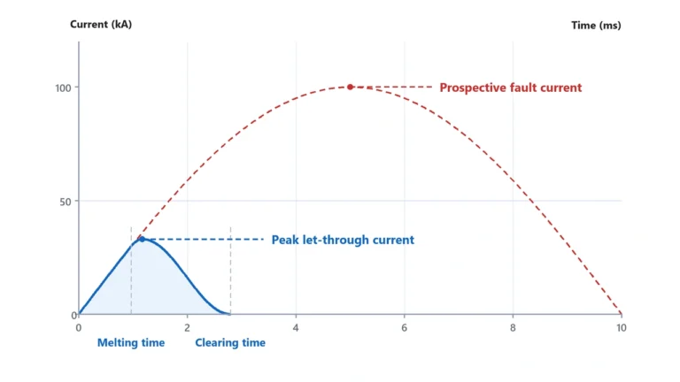
Where downstream equipment coordination is important, peak let-through current and I²t may also matter.
These parameters are explained in our Current Limiting Fuse Guide.
Common PV Fuse Box Design and Sizing Mistakes
Using One Fuse After All Strings Are Combined
One common output fuse cannot provide the same protection as individual string fuses against reverse current entering one faulted string.
Where string protection is required, the fuse needs to be located in the individual string circuit.
Selecting String Fuse Size From Total Array Current
A string fuse protects an individual string.
Do not multiply the string fuse current by the number of parallel strings.
Combined current matters at the busbar and output circuit.
Using the Module Maximum Fuse Rating as the Automatic Fuse Size
A module marked:
Maximum Series Fuse Rating: 25 A
does not automatically require a 25 A fuse.
It establishes an upper protection limit.
Ignoring the Fuse Holder
Correct fuse:
20 A / 1000 V gPV
plus incorrect holder:
600 V
still produces an unsuitable protection assembly.
Treating the SPD as Overcurrent Protection
An SPD and gPV fuse have different protection functions.
Neither automatically replaces the other.
Assuming Every Combiner Needs Output Overcurrent Protection
The requirement depends on available fault sources, conductor ampacity and complete system topology.
Do not add an output fuse only because a typical diagram shows one.
Ignoring Internal Temperature
Outdoor combiner boxes can experience substantial temperature rise.
Heat comes from:
- direct solar exposure;
- fuse power loss;
- terminal resistance;
- SPD;
- breakers;
- tightly grouped devices.
Use manufacturer temperature and derating data rather than assuming nameplate current remains unchanged at every ambient temperature.
Confusing Fuse Holder With Disconnect Switch
A hinged fuse holder is not automatically suitable for opening a live high-voltage DC circuit.
Only operate it under load if the manufacturer explicitly rates the device for that function.
PV Fuse Box Selection Checklist
Before specifying a PV fuse box or combiner configuration, collect the system data first.
PV Array Data
Module model
→ Isc
→ Voc
→ Maximum series fuse rating
→ Voc temperature coefficient
String configuration
→ Modules per string
→ Number of parallel strings
Environmental data
→ Minimum design temperature
→ Maximum enclosure temperature
String Fuse Data
Confirm:
- required OCPD;
- fuse current;
- maximum DC voltage;
- gPV classification;
- breaking capacity;
- physical fuse size;
- fuse-holder compatibility.
Combiner Data
Confirm:
- number of inputs;
- number of outputs;
- busbar current;
- output conductor size;
- SPD requirement;
- output protection requirement;
- switching or isolation requirement;
- enclosure IP requirement;
- cable entry;
- internal thermal capacity.
Example Specification Flow
A project inquiry should ideally look like:
4 PV strings
→ Module Isc: 12.5 A
→ Maximum series fuse: 25 A
→ Maximum system voltage: 1000 V DC
→ 20 A gPV string fuse example
→ 4 protected inputs
→ combined-output conductor sized for array current
→ SPD / output device selected according to project requirements
rather than:
Need a 4-string solar fuse box.
That description alone does not define enough electrical parameters for safe component selection.
For project-specific enclosure and internal protection configurations, see UHCCY PV Combiner Box.
For individual gPV fuse-links and compatible DIN-rail fuse holders, see DC Fuse.
The key principle is to treat the combiner as one coordinated DC protection system:
PV String → String Fuse → Fuse Holder → Busbar → Output Protection → Cable → Inverter
rather than selecting each component independently from its headline current rating.