Table of Contents
A DC fuse disconnector and a DC fuse holder can look similar, especially in DIN-rail photovoltaic equipment, but they should not automatically be treated as the same device.
A fuse holder primarily provides the electrical contacts, terminals and mechanical support required to install a replaceable fuse-link. A fuse disconnector adds a defined isolation function, allowing the fuse or fuse carrier to form part of a device designed to create an isolating separation.
The distinction becomes important in solar PV systems because opening a fuse carrier does not automatically mean that the device is approved for switching a live DC circuit.
The practical rule is:
Fuse holder ≠ automatically a disconnector
and:
Fuse disconnector ≠ automatically a load-break switch
The exact function must be confirmed from the manufacturer’s ratings, applicable standard and product documentation.
For the basic relationship between fuse current, voltage and breaking capacity, see our DC Fuse Guide.
What Is a DC Fuse Disconnector?
A DC fuse disconnector combines fuse protection with a defined disconnecting or isolating function.
In IEC terminology, fuse-combination devices are covered by the current IEC 60947-3, which addresses switches, disconnectors, switch-disconnectors and fuse-combination units for circuits up to 1500 V DC.
The terminology matters because several related devices exist.
Fuse-Disconnector
In a fuse-disconnector, the fuse-link or the fuse carrier containing the fuse-link forms part of the moving contact system.
Its open position provides a defined isolating function when the product is designed and rated accordingly.
Disconnector-Fuse
A disconnector-fuse combines a disconnector with one or more fuses connected in series as a composite unit.
The fuse itself does not necessarily form the moving contact.
Fuse-Switch-Disconnector
This adds another important capability:
switching + isolation + fuse protection
A switch-disconnector is designed not only to provide an isolating function but also to make and break current under its specified utilization conditions.
This distinction is critical.
A product described only as a:
fuse holder
or even:
fuse disconnector
should not automatically be used as an on-load switch unless its ratings explicitly permit that operation.
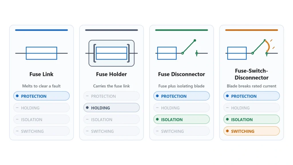
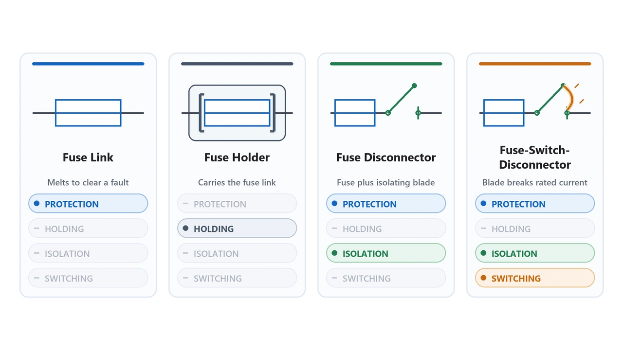
DC fuse disconnector vs fuse holder comparisonFuse Link vs Fuse Holder vs Fuse Base vs Fuse Disconnector
These terms are frequently used interchangeably in supplier listings, but technically they describe different parts or functions.
| Term | Main Function | Contains Fuse Link? | Isolation Function? | Load Switching? |
|---|---|---|---|---|
| Fuse link | Overcurrent protection | It is the fuse | No | No |
| Fuse holder | Mounts and connects fuse | Yes, when installed | Not automatically | Not automatically |
| Fuse base | Fixed contacts/base for fuse system | Fuse installed onto base | Not automatically | No |
| Fuse disconnector | Protection + isolation | Yes | Yes, when correctly rated | Not necessarily |
| Fuse-switch-disconnector | Protection + isolation + switching | Yes | Yes | Yes, within rating |
Fuse Link
The fuse-link is the replaceable protective element.
For photovoltaic applications this may be, for example:
gPV fuse-link
with ratings such as:
20 A / 1000 V DC / gPV
or:
20 A / 1500 V DC / gPV
The fuse-link is normally replaced after it operates.
For the PV utilization category, see our gPV Fuse Guide.
Fuse Holder
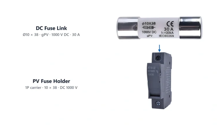
A fuse holder provides:
- electrical contacts;
- cable terminals;
- mechanical retention;
- insulation;
- a method for inserting and removing the fuse.
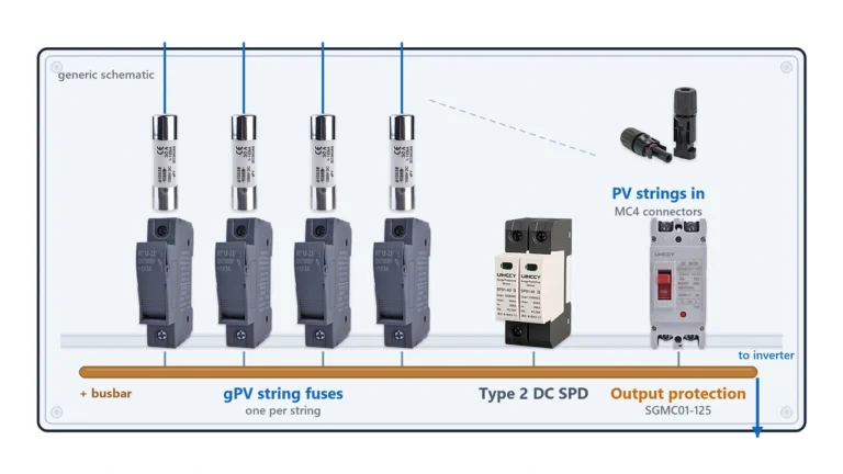
DIN-rail cylindrical PV fuse holders are commonly used inside combiner boxes and DC distribution enclosures.
A holder can have a hinged, pull-out or rotating carrier while still being classified primarily as a fuse holder.
The presence of a movable handle does not by itself prove that the holder is suitable for switching load current.
Fuse Base
The term fuse base is especially common with larger industrial fuse systems such as NH fuse-links.
The base provides stationary contacts and terminals onto which the fuse-link is fitted.
Current IEC 60269-2 covers a number of standardized industrial fuse systems, including cylindrical, blade-contact and fuse-base arrangements.
A fuse base should not automatically be described as a disconnector.
Fuse Disconnector
A fuse disconnector integrates a defined isolating function.
The open state must meet the applicable requirements for isolation rather than simply exposing or removing the fuse.
This makes terminology particularly important in procurement documents.
If a project requires:
isolation
do not specify only:
fuse holder
and assume both mean the same thing.
DC Fuse Holder vs Fuse Disconnector: Which One Do You Need?
The correct choice depends on what the device is expected to do.
Use a Fuse Holder When
The system mainly requires:
- fuse mounting;
- fuse replacement;
- conductor termination;
- compact DIN-rail installation;
- overcurrent protection through the fuse-link.
This is common in:
- PV combiner boxes;
- DC distribution boxes;
- inverter protection assemblies;
- OEM control panels.
If separate isolation is already provided elsewhere in the system, a dedicated fuse holder may be sufficient.
Use a Fuse Disconnector When
The design specifically requires:
- fuse protection;
- a defined isolating position;
- safer separation for maintenance;
- an integrated fuse-and-isolation device.
However, check exactly what type of disconnector is being specified.
A disconnector primarily provides isolation.
It is not automatically designed to interrupt normal load current.
Use a Fuse-Switch-Disconnector When
The design requires all three functions:
Fuse protection → switching → isolation
This can be useful where one device must provide both overcurrent protection and routine switching or maintenance isolation.
The correct utilization category and DC rating must be confirmed for the actual operating duty.
For applications where a resettable protective device is being considered instead, see Fuse vs Circuit Breaker.
Can a DC Fuse Holder Be Used as a Disconnect Switch?
This is one of the most important practical distinctions in the entire topic.
Not unless the manufacturer explicitly rates the device for that function.
Many DIN-rail fuse holders have handles or carriers that can physically be opened.
That does not automatically mean they should be operated while current is flowing.
Opening a DC circuit can create an arc.
In a high-voltage PV system, that arc can be significantly more difficult to extinguish than in an AC circuit because DC does not provide regular natural current-zero crossings.
Therefore, using an ordinary fuse holder as a load-break switch may expose the device to a duty it was never designed to perform.
The safe decision process is:
Does the device only hold a fuse?
→ treat it as a fuse holder.
Is it specifically rated as a disconnector?
→ it may provide isolation according to its rated function.
Is it specifically rated as a switch-disconnector or fuse-switch-disconnector?
→ it may make and break current within its specified utilization rating.
Do not derive switching capability from the presence of a handle.
Do Not Pull a Fuse Under Load Unless Rated
Removing a live fuse-link can expose:
- the fuse carrier;
- contacts;
- surrounding insulation;
- the operator;
to an electrical arc.
This is especially serious in 1000 V and 1500 V photovoltaic systems.
A fuse holder intended primarily for fuse replacement should normally be de-energized according to the manufacturer’s procedure before the fuse is removed.
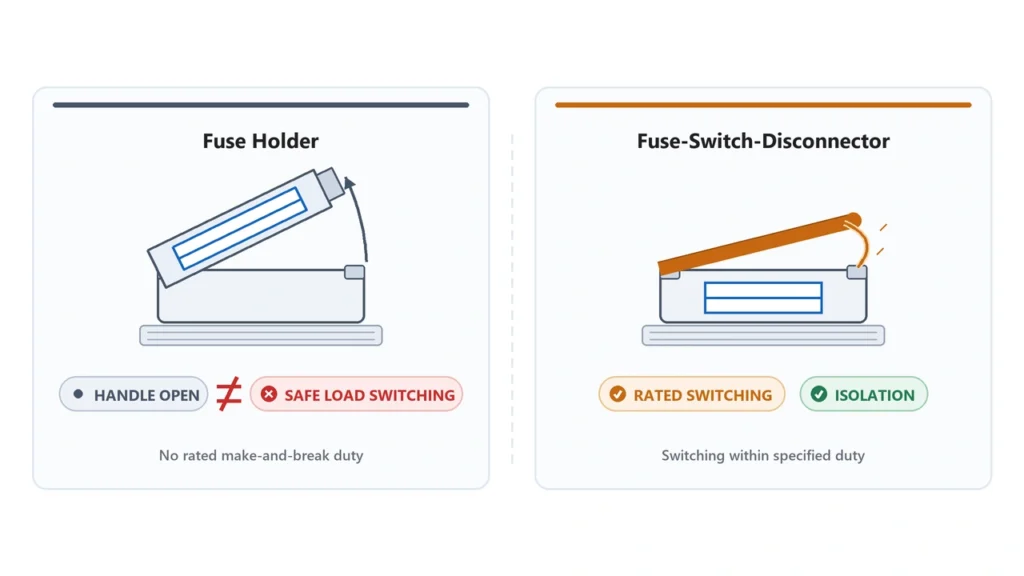
DC fuse holder is not automatically a load break switchHow to Select a DC or PV Fuse Holder
A fuse holder should be treated as an electrical component with its own ratings—not merely as a plastic shell around the fuse.
Check at least the following.
1. DC Voltage Rating
The holder must be rated for the actual DC system voltage.
For example:
1000 V fuse + 600 V holder = not a 1000 V protection assembly
The system rating is limited by the component with the lowest applicable rating.
Likewise:
1500 V fuse + 1000 V holder ≠ 1500 V system
For PV voltage selection, see 1000V Solar Fuse vs 1500V.
2. Rated Current
Fuse-holder current rating and fuse-link current rating are separate parameters.
A holder rated for 32 A may accommodate several lower-current fuse-links, but the actual usable combination still depends on:
- fuse power loss;
- conductor size;
- ambient temperature;
- enclosure temperature;
- adjacent devices.
Do not assume:
32 A holder = every 32 A fuse can operate continuously under every condition
3. Fuse Dimensions
The fuse must physically match the holder.
Common cylindrical PV fuse formats include:
- 10 × 38 mm;
- 14 × 51 mm;
- 10 × 85 mm;
- 14 × 85 mm.
Larger NH-style PV fuses use completely different fuse bases.
Physical dimensions are therefore part of the electrical selection process.
4. Fuse Type
The holder should be intended for the applicable fuse family.
A cylindrical holder designed around a particular PV fuse format should not be assumed suitable for any cartridge fuse of similar diameter.
5. Breaking Withstand Capability
The fuse performs the primary interruption, but the holder must survive the electrical and mechanical stresses associated with the fault.
Check the holder manufacturer’s specified withstand or short-circuit-related ratings as applicable.
6. Terminal Range
Confirm:
- minimum conductor size;
- maximum conductor size;
- solid or stranded conductor acceptance;
- ferrule requirements;
- terminal torque.
Poor termination can cause additional contact resistance and heating even when the fuse rating itself is correct.
7. Number of Poles
PV holders may be:
- 1-pole;
- 2-pole;
- multi-pole assemblies.
The number of protected conductors depends on the system grounding and protection architecture.
Do not automatically assume every PV circuit requires identical fuses in both positive and negative conductors.
8. Indicator Function
Some holders include:
- LED indication;
- neon indication;
- mechanical fuse-status indication.
An indication circuit may have its own operating range and should not be confused with the actual protection function.
9. DIN-Rail Mounting
A DIN rail fuse holder is particularly useful in modular protection equipment such as:
- PV combiner boxes;
- DC distribution boards;
- OEM enclosures.
Check both DIN-rail compatibility and module width when designing enclosure capacity.
1000V vs 1500V PV Fuse Holders
Voltage class affects more than the fuse-link.
Higher-voltage protection systems can require:
- greater creepage distance;
- greater clearance;
- increased insulation capability;
- longer fuse formats;
- different carriers;
- different holder dimensions.
This is why 1000 V and 1500 V PV holders are often not interchangeable.
A typical market architecture may use:
1000 V DC
→ compact cylindrical fuse
→ compact DIN-rail holder
while a higher-voltage platform may use:
1500 V DC
→ longer PV fuse-link
→ larger dedicated holder
But the actual dimensions must always be verified from the specific product datasheet.
Do not write a procurement specification such as:
1500 V holder for 10 × 38 fuse
unless the selected manufacturer’s actual product explicitly supports that combination.
Can a 1500V Holder Be Used in a 1000V System?
Potentially, but only if:
- the fuse is compatible;
- current rating is suitable;
- terminal specifications match;
- thermal performance is acceptable;
- physical dimensions suit the enclosure;
- required certifications remain valid.
The higher voltage number alone does not make it a universal replacement.
Can a 1000V Holder Be Used With a 1500V Fuse?
Not for a circuit that requires a 1500 V protection rating.
The complete assembly cannot claim a voltage rating higher than the holder is designed and documented to support.
For available fuse and holder configurations, refer to the UHCCY DC Fuse category.
Thermal Performance and Installation Matter
Fuse holders can become a significant heat source inside compact electrical enclosures.
Heat can originate from:
Fuse element power loss
- contact resistance
- terminal resistance
- adjacent protection devices
This makes installation quality important.
Contact Resistance
Poor fuse-to-holder contact increases resistance.
Higher resistance produces more heat:
P = I²R
Even a relatively small increase in resistance can create significant heating at higher current.
Possible causes include:
- insufficient contact pressure;
- contamination;
- corrosion;
- damaged contacts;
- incorrect fuse dimensions;
- repeated overheating.
Terminal Torque
Under-tightened terminals can increase resistance.
Over-tightening can damage:
- terminal clamps;
- conductors;
- threads;
- housing.
Always use the manufacturer’s specified torque.
Adjacent Devices
Several loaded fuse holders installed side by side can increase local enclosure temperature.
This should be considered when selecting:
- fuse rating;
- holder rating;
- cable size;
- enclosure ventilation;
- device spacing.
Fuse Power Loss
A fuse has measurable power dissipation during normal operation.
The holder must be capable of accepting the thermal load from the installed fuse-link.
This is one reason why physical compatibility alone is insufficient.
Outdoor PV Enclosures
Combiner boxes can be exposed to:
- solar heating;
- high ambient temperatures;
- restricted ventilation;
- continuous current.
The installed thermal environment can therefore be significantly more severe than room-temperature laboratory conditions.
Fuse sizing itself is discussed in our Solar Fuse Sizing Guide.
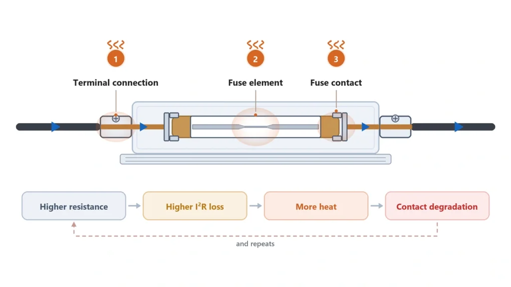
DC fuse holder contact resistance and overheating pointsStandards for PV Fuse Holders and Fuse Disconnectors
The applicable standard depends on what the device actually is.
This is another reason terminology matters.
IEC Fuse Systems
IEC 60269-2 contains supplementary requirements and standardized examples for industrial fuse systems used by authorized persons.
Its current consolidated version includes systems such as:
- blade-contact fuse systems;
- cylindrical fuse systems;
- fuse bases;
- bolted fuse arrangements.
For a photovoltaic application, the fuse-link itself may additionally use the gPV requirements discussed in our gPV Fuse Guide.
Fuse Disconnectors and Fuse-Combination Units
The current IEC 60947-3:2020+A1:2025 covers:
- switches;
- disconnectors;
- switch-disconnectors;
- fuse-combination units;
for systems up to 1000 V AC or 1500 V DC.
If a supplier calls a device a fuse disconnector, the product documentation should support the actual isolating function being claimed.
Likewise, if the product is marketed for switching load current, its appropriate switching function and ratings should be documented.
North American PV Fuse Holders
For North American photovoltaic applications, UL 4248-19 specifically addresses photovoltaic fuseholders used with PV fuse systems.
This is separate from UL 248-19, which addresses the photovoltaic fuse itself.
Therefore:
PV fuse certification ≠ automatically PV fuse-holder certification
and:
fuse-holder certification ≠ certification of the complete combiner box
Each level of the system has its own applicable requirements.
Choosing a DC Fuse Holder or Disconnector for a Project
For OEM, combiner-box and B2B procurement, avoid an RFQ that simply says:
Need 20 A DC fuse holder.
That leaves too many critical parameters undefined.
A useful specification should include:
Application
→ PV string / combiner / industrial DC circuit
Maximum DC voltage
→ 1000 V / 1500 V / other calculated value
Fuse rating
→ current + type + dimensions
Holder function
→ holder only / isolation required / load switching required
Number of poles
Cable size
Terminal type
DIN rail or panel mounting
Indicator requirement
Expected ambient temperature
Applicable IEC / UL requirements
Certification requirement
The required product might then be specified more accurately as:
DIN-rail PV fuse holder for 10 × 38 mm gPV fuse
rather than simply:
DC fuse holder
or, where isolation is required:
DC fuse disconnector with defined isolation function
and where switching is also required:
fuse-switch-disconnector with the required DC utilization rating
This distinction prevents one of the most common procurement errors in DC protection:
buying a component that physically holds the fuse but does not provide the switching or isolation function expected by the system designer.
For available UHCCY fuse-links and compatible bases or holders, see the DC Fuse range.