Table of Contents
This DC Fuse Guide explains how DC fuses work, how to select voltage and current ratings, and how photovoltaic fuses protect solar PV strings and arrays. A DC fuse is an overcurrent protection device designed to interrupt excessive current before conductors, equipment or connected components are damaged.
Although the operating principle appears simple—a calibrated fuse element melts when excessive current flows—selecting a DC fuse requires more than choosing an ampere rating. System voltage, prospective fault current, fuse utilization category, breaking capacity, operating temperature, conductor ampacity and the protected equipment all influence the correct choice.
These considerations become particularly important in photovoltaic systems. Solar arrays operate at sustained DC voltages, can be exposed to wide temperature variations and may produce fault currents that behave differently from conventional AC circuits.
This guide explains how DC fuses work, how they differ from AC fuses, how photovoltaic gPV fuses are classified, and how to evaluate voltage, current and breaking capacity when selecting protection for a DC or solar PV system.
For available photovoltaic fuse links and compatible protection components, see our DC Fuse range.
What Is a DC Fuse?
A DC fuse is a sacrificial overcurrent protection device installed in series with a DC circuit.
Under normal operating conditions, current passes through a conductive fuse element. When current exceeds the fuse’s time-current characteristic for a sufficient period, the element melts and separates.
Opening the element is only the first stage.
After the fuse element melts, an electrical arc may form across the resulting gap. The fuse must extinguish that arc safely and withstand the circuit voltage after interruption.
This requirement is one of the main reasons DC fuse selection differs from AC fuse selection.
A correctly selected DC fuse can provide protection against conditions such as:
- short circuits;
- excessive reverse current;
- conductor overcurrent;
- equipment faults;
- faults between parallel DC sources.
The fuse should be considered part of a complete protection system rather than an isolated component. Conductors, fuse holders, disconnectors, terminals and downstream equipment must all be rated for the same application.
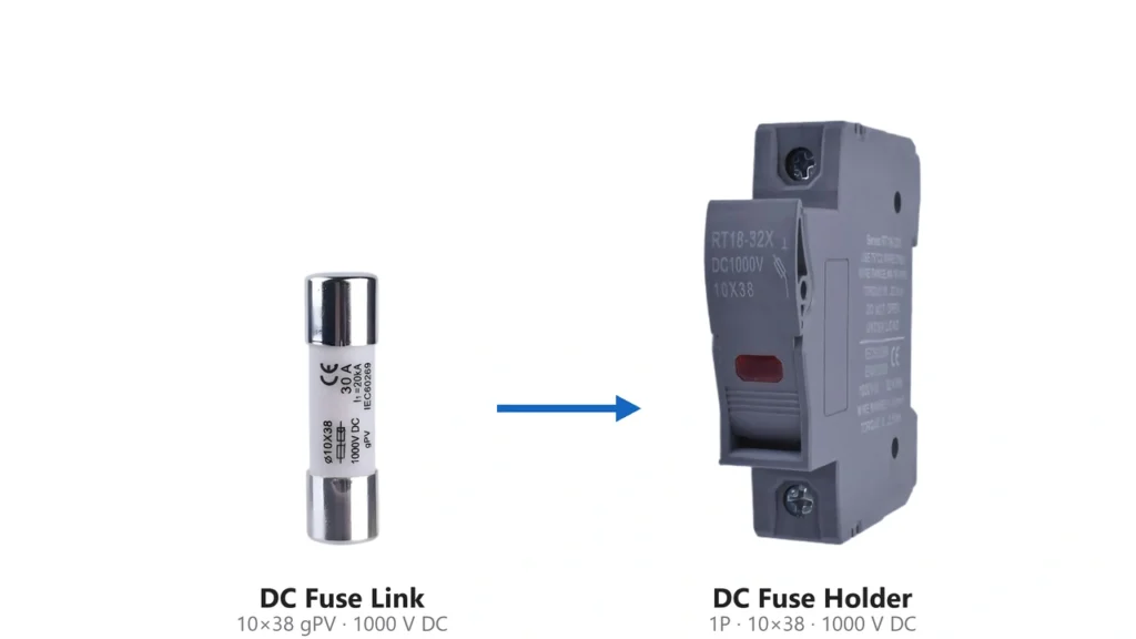
DC Fuse Guide for solar PV fuse links and fuse holdersHow Does a DC Fuse Work?
The fuse element is engineered to respond predictably to current and time.
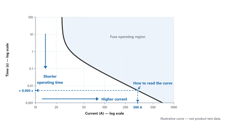
A small temporary overcurrent may be tolerated for a defined period, while a sufficiently large fault causes the element to melt much faster. This relationship is represented by the manufacturer’s time-current curve.
When interruption occurs, three processes take place:
- excessive current heats the fuse element;
- the element melts and creates one or more gaps;
- the fuse extinguishes the resulting electrical arc.
The third process is particularly important in DC systems.
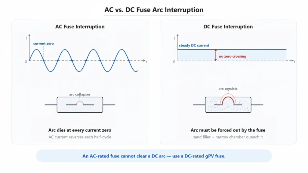
An AC waveform naturally passes through zero current every half-cycle. This assists arc extinction. Direct current does not provide this natural periodic current zero, so a DC-rated fuse must be capable of interrupting and extinguishing the arc under continuous DC voltage. Eaton describes this difference directly in its fuse technical guidance.
This is why the voltage marking on a fuse is not merely an insulation rating. It is also related to the fuse’s ability to interrupt a fault safely at that voltage.
DC Fuse vs AC Fuse: What Is the Difference?
A fuse rated for AC should not automatically be assumed suitable for a DC circuit.
The fundamental difference is the behavior of the electrical arc after the fuse element opens.
In AC systems, current repeatedly crosses zero. In DC systems, current continues in the same direction without that natural zero crossing. A sustained DC arc can therefore be more difficult to extinguish.
This means a DC protection device may require different internal dimensions, arc-extinguishing media, fuse-element geometry and separation distance.
The practical rule is straightforward:
Use a fuse with an explicit DC voltage rating suitable for the circuit. Do not convert an AC voltage rating into a DC rating unless the manufacturer explicitly provides an approved DC rating.
The ampere rating alone does not determine whether a fuse is appropriate.
For example, two fuses may both be marked 20 A but have very different voltage ratings, breaking capacities and application classes.
Difference between AC and DC fuse arc interruptionWhat Is a Solar or PV Fuse?
A photovoltaic fuse is a DC fuse specifically designed for the operating characteristics of solar PV systems.
PV circuits can combine:
- relatively high DC system voltage;
- limited fault current from PV modules;
- reverse current from parallel strings;
- repeated daily thermal cycling;
- high equipment temperatures;
- continuous outdoor operation.
For these reasons, photovoltaic protection has its own fuse requirements.
IEC 60269-6 defines supplementary requirements for fuse-links used to protect photovoltaic strings and arrays in circuits with nominal voltages up to 1,500 V DC.
North American photovoltaic fuse requirements are addressed by UL 248-19, which remains an active standard and was revised in November 2024. Its scope covers fuses intended to protect photovoltaic strings, arrays and associated wiring.
These standards should not be interpreted as automatic proof that any particular UHCCY product is certified. Product certification must be supported by the corresponding certificate or test documentation.
What Does gPV Mean?
gPV is the IEC utilization category specifically associated with photovoltaic fuse-links.
The designation is important because it describes the type of duty for which the fuse has been designed and tested.
In IEC fuse terminology:
- g indicates full-range breaking capability;
- PV identifies the photovoltaic application.
A gPV fuse is therefore intended to provide full-range DC breaking capability for photovoltaic protection.
This distinction matters because PV arrays can produce relatively low fault currents compared with many conventional power systems. Eaton and Mersen both describe photovoltaic fuse designs as being specifically engineered to interrupt the unusual low-fault-current conditions found in PV systems.
A generic cartridge fuse that physically fits a holder should therefore not automatically be treated as a gPV fuse.
Why Do Solar PV Systems Need Specialized Fuses?
A common misconception is that a solar fuse only protects the inverter from a short circuit.
Its role is broader.
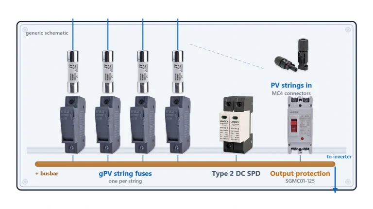
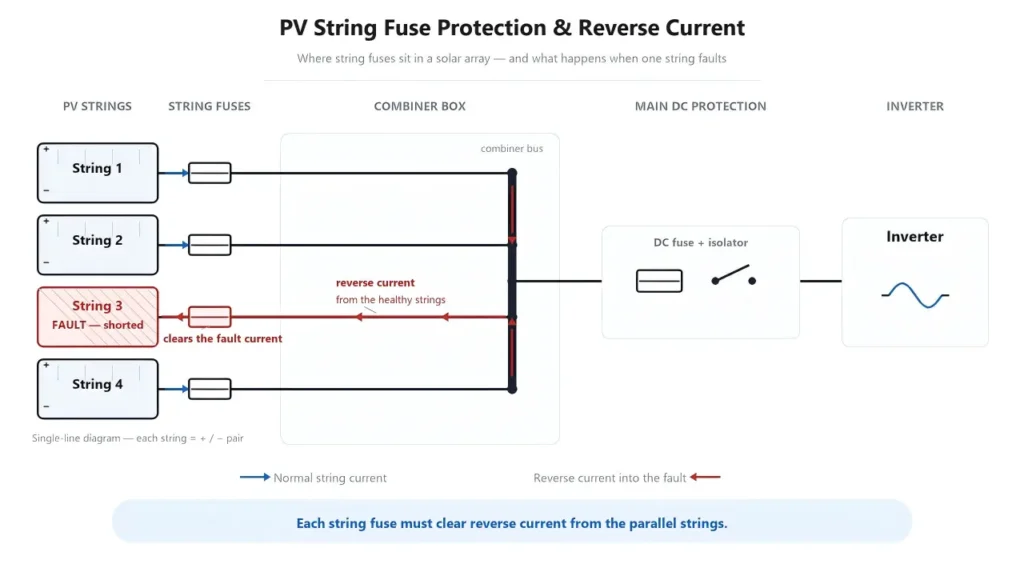
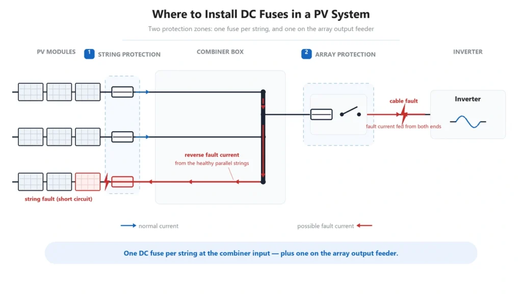
In a PV array, several strings can be connected in parallel. If one string develops a fault, current can potentially flow into that string from the remaining parallel strings.
This reverse current can exceed what the affected module conductors or wiring are designed to withstand.
PV fuses can therefore be used to isolate a faulted string before reverse current damages wiring or modules.
Other applications can include:
- PV string protection;
- array and sub-array protection;
- combiner boxes;
- recombiner equipment;
- inverter DC inputs where applicable;
- dedicated in-line PV protection.
The specific fuse position and rating depend on the system architecture.
Solar PV string fuse protection and reverse current diagramDoes Every Solar Panel Need a Fuse?
No.
A fuse is not automatically required simply because a PV module is installed.
Whether overcurrent protection is required depends on the possible current from all connected sources, conductor ampacity, the module’s permitted overcurrent protection, the array configuration and the applicable electrical code.
NEC Article 690.9, for example, provides conditions under which PV DC circuits may not require a separate overcurrent protective device when the conductor can carry the maximum circuit current and the available current from connected sources cannot exceed the applicable protection limits.
As more strings are connected in parallel, the possible reverse current into a faulted string increases.
For this reason, string fusing becomes particularly relevant in multi-string arrays.
However, using a fixed rule such as “every solar panel needs a fuse” or “all systems with a certain number of panels require a fuse” is too simplistic.
The design should instead be checked against:
- module short-circuit current, Isc;
- module maximum series fuse or overcurrent rating;
- number of parallel current sources;
- conductor ampacity;
- inverter and combiner architecture;
- applicable code requirements.
DC Fuse Guide: How to Select the Right Fuse
Selecting a DC fuse should be treated as a multi-parameter engineering decision.
1. Determine the Maximum DC System Voltage
The fuse’s rated DC voltage must be at least equal to the maximum voltage that can appear across the device.
For PV systems, this is not necessarily the same as the nominal array voltage.
Module open-circuit voltage increases as module temperature falls. String voltage therefore needs to be evaluated under the minimum expected operating temperature.
A 1,000 V DC or 1,500 V DC fuse should consequently be selected according to the actual maximum circuit voltage and system design—not simply because one rating is “better” than another.
Never use a fuse above its rated DC voltage.
2. Determine the Maximum Operating Current
The fuse must carry the normal operating current without unnecessary operation.
At the same time, it must be low enough to protect the conductor and equipment during abnormal conditions.
In PV applications, module short-circuit current (Isc) is normally an important starting value.
For NEC-based PV source-circuit sizing, a commonly used calculation applies one 125% factor to obtain maximum circuit current and another 125% factor for overcurrent-device loading:
1.25 × 1.25 = 1.5625
This is commonly simplified to:
Fuse sizing basis ≈ 1.56 × Isc
Littelfuse’s photovoltaic fuse-sizing guidance uses this 1.56 × Isc method for PV source circuits.
However, 1.56 × Isc is not a universal fuse-selection formula.
The selected rating must also comply with the module’s permitted series-fuse rating, conductor ampacity, equipment ratings, environmental derating and the electrical code applicable to the installation.
3. Check the Maximum Series Fuse Rating of the PV Module
PV module manufacturers normally specify the maximum permitted overcurrent protective-device or series-fuse rating.
The selected string fuse must not exceed the module manufacturer’s allowed value.
This creates an important selection window:
the fuse must be large enough to carry normal maximum circuit current, but small enough to remain within the module and conductor protection limits.
Selecting the next available fuse size solely because the calculated operating current is higher is not sufficient unless all upper limits are also satisfied.
4. Check Breaking Capacity
Breaking capacity, sometimes called interrupting rating, defines the maximum prospective fault current the fuse can safely interrupt under specified conditions.
This parameter is different from rated current.
For example:
- rated current determines the normal current level associated with the fuse;
- breaking capacity determines how large a fault the fuse can safely interrupt.
The required breaking capacity must be evaluated against the prospective short-circuit current at the installation point.
Battery systems deserve particular attention because batteries can supply very high fault current.
A fuse suitable for a PV string should not automatically be assumed suitable for a high-current battery circuit simply because the voltage and ampere markings appear similar.
DC Fuse Ratings You Should Check
A professional fuse specification should contain more than voltage and current.
Important parameters include:
| Parameter | Why It Matters |
|---|---|
| Rated DC voltage | Maximum voltage the fuse is designed to interrupt |
| Rated current | Nominal current classification of the fuse |
| Breaking capacity | Maximum prospective fault current the fuse can safely interrupt |
| Utilization category | Identifies the intended protection duty, such as gPV |
| Time-current characteristic | Shows how quickly the fuse operates at different overcurrents |
| I²t | Indicates the thermal energy let-through during operation |
| Power loss | Influences heat generation during normal operation |
| Fuse dimensions | Must match the intended holder or mounting system |
| Temperature characteristics | May require current derating at elevated ambient temperature |
| Applicable standard | Defines the testing and classification basis |
For procurement, a fuse should therefore never be selected solely from a description such as “20 A DC fuse.”
What Is I²t?
I²t represents the thermal energy associated with current flowing during the fuse operating process.
It is derived from current squared over time.
Manufacturers may provide values such as:
- pre-arcing I²t;
- total clearing I²t.
Lower let-through energy can help reduce the thermal and mechanical stress applied to protected components during a fault.
However, I²t values should be compared using the manufacturer’s specified test conditions. They should not be treated as a simple universal “lower is always better” ranking between unrelated fuse families.
For ordinary PV string selection, voltage, current, utilization category, module protection limits and breaking capacity are usually considered before detailed I²t coordination.
1000V vs 1500V DC Fuse
The difference between a 1,000 V and 1,500 V photovoltaic fuse is not simply the printed voltage.
A higher-voltage fuse must safely extinguish an arc and withstand a higher recovery voltage after interruption.
This often affects internal construction and physical dimensions.
Common photovoltaic fuse formats include cylindrical cartridge designs, but dimensions vary according to voltage, current and manufacturer.
For example, commercial PV fuse families exist in formats such as 10 × 38 mm and 10 × 85 mm. Eaton lists 1,500 V DC gPV products in a 10 × 85 mm format, while other manufacturers offer 1,000 V DC gPV cartridge formats.
These examples describe industry products, not UHCCY specifications.
The correct selection rule remains:
Choose the voltage class from the calculated maximum circuit voltage, then verify current, breaking capacity, utilization category and holder compatibility.
Do not replace a 1,000 V fuse with a 1,500 V fuse purely on the assumption that the higher number is automatically preferable. Physical compatibility, thermal characteristics, approvals and equipment coordination must also be checked.
DC Fuse Holder vs Fuse Link
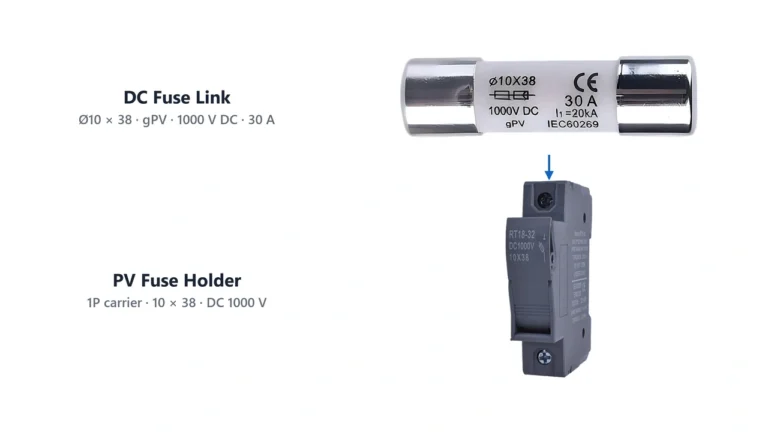
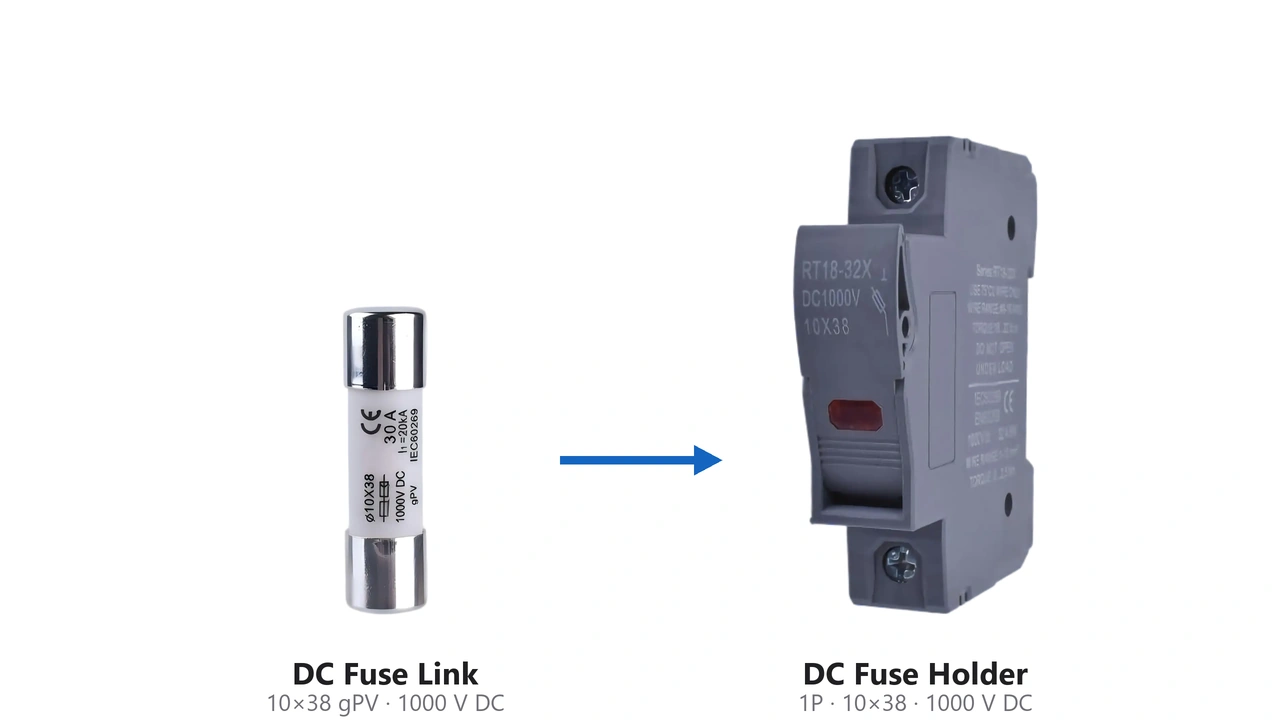
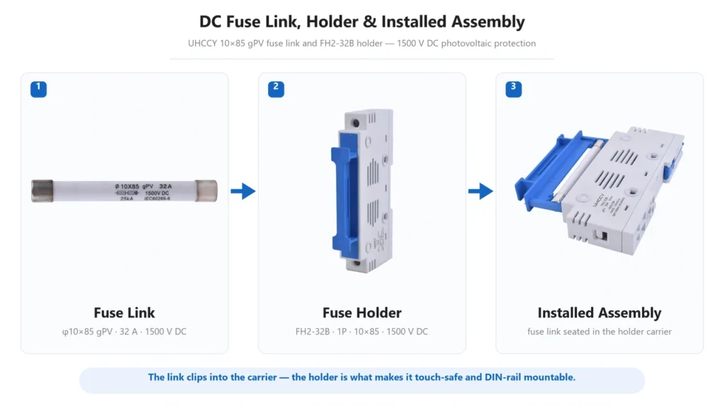
The fuse link is the replaceable overcurrent-protection element.
The fuse holder provides mechanical mounting and electrical connection for the fuse link.
Some products also combine the holder with a manually operated disconnection function and may be described as fuse disconnectors.
These components should not be treated as interchangeable terminology.
A correct pairing requires checking:
- fuse dimensions;
- current rating;
- DC voltage rating;
- thermal performance;
- terminal capacity;
- applicable fuse class;
- manufacturer compatibility requirements.
A fuse that physically fits inside a holder is not automatically an electrically valid combination.
For compatible photovoltaic fuse links and holder options, refer to the DC Fuse product category.
DC fuse link fuse holder and assembled photovoltaic fuse protectionDC Fuse vs Circuit Breaker
Both fuses and circuit breakers can provide overcurrent protection, but they are not identical devices.
A fuse:
- operates by melting a calibrated element;
- must normally be replaced after operation;
- can provide high interruption capability in a compact device;
- has no mechanical reset mechanism.
A circuit breaker:
- uses a mechanical switching mechanism;
- can normally be reset after operation;
- can provide switching and isolation functions depending on its design;
- has its own trip curves and DC arc-extinguishing requirements.
The choice should be based on the system architecture rather than a general claim that one technology is always superior.
PV systems may use both.
For example, individual strings may use gPV fuses while other parts of a DC distribution system use appropriately rated DC circuit breakers or disconnectors.
Every protective device must be specifically rated for its actual DC duty.
Where Should a DC Fuse Be Installed?
A fuse should normally be placed so that it protects the conductor or equipment from the point where damaging overcurrent can enter the circuit.
Possible PV locations include:
- individual strings;
- combiner-box inputs;
- array outputs;
- recombiner circuits;
- specific inverter DC inputs;
- in-line module circuits where the system design requires them.
The exact location depends on where fault current can originate.
This is especially important when a conductor is connected to multiple energy sources. Installing a fuse far from the source of damaging fault current may leave part of the conductor insufficiently protected.
System drawings should therefore identify both the protected conductor and every source capable of feeding the fault.
DC fuse installation locations in a solar PV systemWhy Does a DC Fuse Keep Blowing?
A blown fuse is usually a symptom rather than the root cause.
Possible causes include:
- short circuit;
- insulation failure;
- reverse current from parallel sources;
- incorrect fuse rating;
- loose or overheated connection;
- incompatible fuse holder;
- abnormal equipment current;
- repeated thermal cycling;
- incorrect system configuration.
Repeatedly replacing a fuse without identifying the underlying fault can create a safety risk.
If a fuse opens repeatedly, verify the circuit before installing another fuse of the same rating.
Never solve repeated fuse operation by simply installing a higher-current fuse unless the entire protection design has been recalculated and the higher rating remains within the conductor and equipment limits.
DC Fuse Selection Checklist
Before specifying or purchasing a DC fuse, confirm:
- maximum operating DC voltage;
- normal and maximum circuit current;
- prospective fault current;
- required breaking capacity;
- fuse utilization category;
- conductor ampacity;
- protected equipment’s maximum permitted overcurrent rating;
- ambient temperature and derating;
- fuse dimensions;
- compatible fuse holder or disconnector;
- applicable IEC, UL or local installation requirements;
- required product certification and supporting documentation.
For solar PV procurement, also provide the module Isc, module maximum series-fuse rating, number of parallel strings and maximum system voltage.
These values allow the fuse supplier and system designer to evaluate the application rather than selecting protection from ampere rating alone.
Choosing DC Fuses for Solar PV Projects
For distributors, OEMs, EPC contractors and panel builders, the best purchasing specification should identify the complete application rather than asking only for a particular current.
A useful RFQ should include:
- application: PV string, array, combiner or other DC circuit;
- system voltage;
- fuse current requirement;
- expected fault-current level;
- fuse dimensions;
- holder requirement;
- applicable standard;
- certification requirements;
- quantity and packaging;
- OEM or marking requirements.
This reduces the risk of receiving a fuse that is mechanically similar but electrically unsuitable.
UHCCY supplies DC protection components for photovoltaic and other DC electrical applications. Available fuse-link and holder configurations can be reviewed in our DC Fuse category.
For a specific project, final fuse selection should always be verified against the protected equipment, conductor design, applicable electrical code and the manufacturer’s technical documentation.