Table of Contents
Solar fuse sizing requires more than multiplying the solar panel current by a fixed number. A correctly selected PV fuse must carry the expected operating current while remaining within the limits of the PV module, conductor, fuse holder and complete DC system.
For many NEC-based photovoltaic source circuits, a commonly used starting point is:
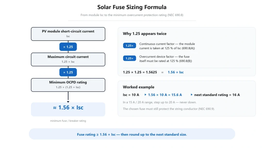
Fuse current ≥ 1.56 × module Isc
But this formula is only one part of the selection process. The resulting fuse must also stay below the module’s maximum series fuse rating, remain compatible with conductor ampacity, withstand the maximum DC system voltage and maintain adequate current-carrying capability at the actual installation temperature.
This guide explains the complete process.
If you first need to determine whether a PV string actually requires overcurrent protection, see our Solar Panel Fuse Guide. For the operating principles and different DC fuse ratings, start with the DC Fuse Guide.
Solar Fuse Sizing: What Determines the Correct Rating?
A photovoltaic fuse cannot be selected from solar panel wattage alone.
The main values you need are:
- module short-circuit current (Isc);
- module open-circuit voltage (Voc);
- maximum series fuse rating;
- number of modules in series;
- number of parallel strings;
- conductor ampacity;
- minimum expected module temperature;
- maximum expected fuse ambient temperature;
- required DC system voltage;
- fuse-holder ratings.
The fuse must satisfy several limits at the same time.
A useful way to think about the selection is:
Minimum required fuse current ≤ selected fuse rating ≤ maximum permitted protection rating
while also ensuring:
Fuse voltage rating ≥ maximum possible system voltage
and:
Fuse rating ≤ permitted conductor protection limit
This means fuse sizing is not simply about finding a minimum ampere value. There must be a valid selection window between the minimum required current and the maximum allowable protection.
Step 1: Determine Whether the PV Circuit Needs a Fuse
Before calculating fuse size, first determine whether overcurrent protection is required.
A single PV string is a current-limited source. The protection problem becomes more significant when multiple strings operate in parallel because healthy strings can feed reverse current into a faulted string.
The current NFPA 70, National Electrical Code allows certain PV circuits to operate without a separate overcurrent protective device when the conductor has sufficient ampacity and the currents available from all connected sources cannot exceed the maximum OCPD rating of the protected equipment.
Therefore:
Do not calculate a fuse rating until you have established that a fuse is required.
The reverse-current and parallel-string logic is covered separately in our Solar Panel Fuse Guide.
Step 2: Find Isc on the Solar Module Datasheet
The first current value required for solar fuse sizing is normally the module short-circuit current, or Isc.
Example module data:
| Parameter | Example |
|---|---|
| Maximum power | 450 W |
| Voc | 41.5 V |
| Isc | 11.2 A |
| Maximum series fuse rating | 25 A |
| Maximum system voltage | 1500 V DC |
The values above are an example only. Always use the actual module manufacturer’s datasheet for the project.
Do not substitute operating current Imp for Isc when the applicable sizing method specifically requires short-circuit current.
Why Isc Instead of Panel Wattage?
A solar panel’s power is approximately:
P = V × I
Two 450 W modules can therefore have different operating voltages and currents.
Consequently, queries such as:
- what size fuse for a 100 watt solar panel;
- fuse size for a 200W solar panel;
- 400 watt solar panel fuse size;
cannot be answered accurately from wattage alone.
The module datasheet is required.
Step 3: Calculate Maximum PV Circuit Current
For conventional NEC-based PV source-circuit calculations, module short-circuit current is first increased to account for the maximum expected PV circuit current.
A commonly used calculation is:
Maximum circuit current = 1.25 × Isc
Using the example module:
1.25 × 11.2 A = 14.0 A
The circuit is therefore evaluated using a maximum current of 14 A rather than the module’s 11.2 A STC short-circuit-current value.
The exact method applicable to a project should always follow the electrical code, module listing and system design requirements used in that jurisdiction.
Step 4: Calculate the Minimum Fuse Current Rating
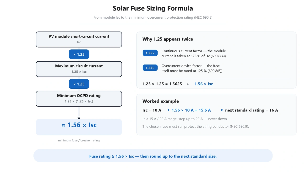
For a conventional NEC method using an overcurrent device that is not part of a listed 100%-rated assembly, the protective-device rating is generally evaluated at not less than 125% of the calculated maximum circuit current.
This produces:
1.25 × 1.25 = 1.5625
usually expressed as:
Fuse rating ≥ 1.56 × Isc
Using our example:
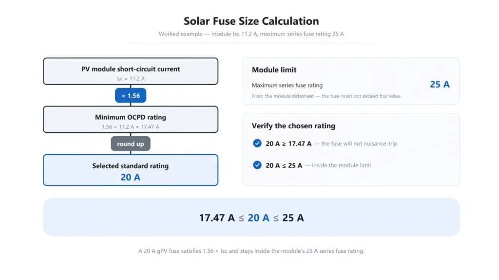
1.56 × 11.2 A = 17.47 A
The calculated minimum is therefore approximately:
17.5 A
Littelfuse uses the same 1.56 × Isc method in its official Photovoltaic Fuse Sizing Guide.
Eaton likewise uses a 1.56 current factor in its Bussmann Series Photovoltaic Application Guide.
1.56 × Isc should not be treated as a universal formula for every DC circuit.
It applies to a particular PV protection methodology. Battery circuits, DC loads, electronic equipment and other DC systems can require different calculations.
Solar fuse sizing formula using 1.56 times PV module IscStep 5: Select the Next Suitable Standard Fuse Rating
Our example produced:
Minimum calculated rating = 17.47 A
The next available standard PV fuse rating might be 20 A, depending on the manufacturer’s product range.
So the preliminary selection becomes:
20 A gPV fuse
However, the calculation is not finished.
Choosing the next standard size is only permitted if that fuse remains within all upper protection limits.
This is where the maximum series fuse rating becomes critical.
Step 6: Check the Maximum Series Fuse Rating
The module datasheet in our example specifies:
Maximum Series Fuse Rating = 25 A
Our preliminary fuse selection is:
20 A
Therefore:
20 A ≤ 25 A
The selected fuse remains within the module manufacturer’s upper protection limit.
The allowable current window in this example is therefore approximately:
17.47 A ≤ fuse rating ≤ 25 A
A standard 20 A gPV fuse falls within that window.
What Does Maximum Series Fuse Rating Mean?
The maximum series fuse rating is not the fuse size you should automatically install.
It is an upper limit.
For example:
Maximum series fuse rating = 25 A
does not mean:
Recommended fuse = 25 A
The fuse still needs to be large enough for normal circuit operation and small enough to provide the intended protection.
This distinction is particularly important for searches such as maximum series fuse rating solar panel and solar panel fuse rating.
Step 7: Check the PV Cable Ampacity
The fuse must also coordinate with the cable it protects.
A fundamental relationship is:
Selected fuse rating ≤ allowable conductor protection limit
A 25 A module limit does not justify installing a 25 A fuse if the installed conductor can only safely support a lower protective-device rating under the actual installation conditions.
Cable ampacity depends on factors such as:
- conductor cross-sectional area;
- conductor material;
- insulation temperature rating;
- ambient temperature;
- cable grouping;
- installation method;
- number of current-carrying conductors;
- applicable electrical standard.
For related PV cable specifications and conductor options, see our Solar Cable range.
The protection system therefore needs to satisfy both:
Fuse ≤ module maximum protection
and:
Fuse ≤ conductor protection limit
Step 8: Apply Fuse Temperature Derating
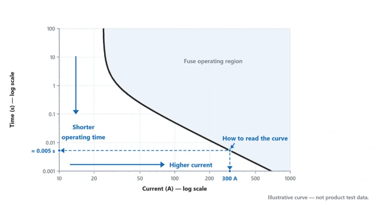
Fuses are thermal devices.
Their current-carrying capability changes with ambient temperature.
This matters in PV installations because fuse holders are often installed inside outdoor combiner boxes where internal temperature can be significantly higher than the surrounding air.
If the fuse manufacturer provides a temperature rerating curve, use that data to verify that the selected fuse can carry the required current at the expected ambient temperature.
Littelfuse explicitly includes temperature derating as a step in its photovoltaic fuse-sizing procedure.
For example, a nominal 20 A fuse does not necessarily mean that it can carry the same continuous current under every enclosure temperature.
The important point is:
Do not simply increase the fuse rating to compensate for temperature.
Any higher rating must still remain within:
- the module maximum series fuse rating;
- conductor protection limits;
- fuse-holder rating;
- equipment protection limits.
If temperature derating eliminates the available selection window, the correct solution may require a different fuse platform, larger conductor, improved enclosure thermal design or another system change.
Step 9: Calculate the Required DC Voltage Rating
Current rating is only half of solar fuse sizing.
The fuse must also safely interrupt the highest DC voltage that can occur in the circuit.
For a PV string:
String Voc = Module Voc × Number of Modules in Series
Suppose:
- module Voc = 41.5 V;
- 20 modules are connected in series.
At STC:
41.5 V × 20 = 830 V
However, this does not automatically mean that a 1000 V fuse is suitable.
PV module open-circuit voltage generally increases as cell temperature falls.
Maximum system voltage therefore needs to account for the minimum expected temperature using:
- the module manufacturer’s voltage-temperature coefficient;
- applicable code temperature correction;
- or another permitted engineering method.
The fuse must then satisfy:
Fuse DC voltage rating ≥ calculated maximum system voltage
Eaton’s PV application guidance commonly uses a preliminary factor of 1.20 × Voc × number of series modules, while also noting that actual project conditions and applicable code requirements must be considered.
Do not use the 1.20 factor as a universal substitute for a proper low-temperature voltage calculation.
1000V vs 1500V Solar Fuse Sizing
The current calculation does not determine whether you need a 1000 V or 1500 V fuse.
Voltage class is determined separately.
For example:
A calculation may produce:
20 A fuse current
but the completed specification could be either:
20 A / 1000 V DC gPV
or:
20 A / 1500 V DC gPV
depending on the maximum circuit voltage.
A 1500 V fuse should not be selected merely because its voltage rating is higher.
Also verify:
- fuse dimensions;
- fuse holder;
- breaking capacity;
- power loss;
- thermal characteristics;
- applicable certification;
- equipment compatibility.
PV fuse-links covered by IEC 60269-6 include fuse requirements for photovoltaic strings and arrays in circuits up to 1500 V DC.
Step 10: Verify gPV Classification and Breaking Capacity
A correctly calculated ampere rating does not make a conventional fuse suitable for a PV string.
Photovoltaic protection commonly uses gPV fuse-links, which are specifically intended for PV string and array protection.
The fuse should also have sufficient breaking capacity for the prospective fault current at its installation point.
This produces a more complete specification:
20 A + required DC voltage + gPV + adequate breaking capacity
rather than simply:
20 A fuse
IEC 60269-6 provides the supplementary requirements for photovoltaic fuse-links, while IEC 62548-1:2023+A1:2025 covers PV array design requirements including DC array wiring and electrical protection devices.
Step 11: Check Fuse Holder Compatibility
The fuse holder is part of the protection system.
Verify:
- fuse physical dimensions;
- holder rated current;
- holder rated DC voltage;
- conductor terminal range;
- installation temperature;
- required poles;
- disconnect function if applicable;
- applicable standards.
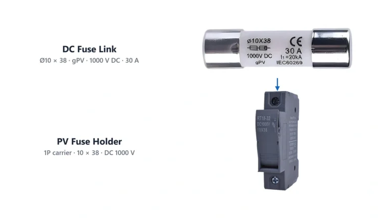
Common photovoltaic fuse dimensions can include formats such as:
10 × 38 mm
and larger formats used for higher voltage or current applications.
A fuse that physically fits into a holder should not automatically be assumed electrically compatible.
Available UHCCY PV fuse links and matching holders can be compared in the DC Fuse category.
Complete Solar Panel Fuse Size Example
Now combine the selection steps.
Module Data
| Parameter | Value |
|---|---|
| Isc | 11.2 A |
| Voc | 41.5 V |
| Maximum series fuse rating | 25 A |
| Maximum system voltage | According to module datasheet |
Array Configuration
| Parameter | Value |
|---|---|
| Modules per string | 20 |
| Parallel strings | 4 |
| String Voc at STC | 830 V |
Current Calculation
Conventional NEC-based minimum:
1.56 × 11.2 A = 17.47 A
Next suitable standard example:
20 A
Module limit:
20 A ≤ 25 A
Current-rating check:
PASS, provided the conductor, fuse holder and temperature conditions also permit 20 A.
Voltage Calculation
STC string Voc:
41.5 × 20 = 830 V
The designer must then calculate maximum cold-weather string voltage.
If the calculated maximum remains below the selected fuse’s rated DC voltage, the voltage requirement can be satisfied.
Preliminary Specification
The result might therefore be:
20 A gPV fuse
with the required system voltage class.
But final selection still requires verification of:
- cold-temperature voltage;
- conductor ampacity;
- ambient-temperature derating;
- fuse holder;
- breaking capacity;
- product certification requirements.
Solar panel fuse size calculation using Isc and maximum series fuse ratingHow to Size a Fuse for Multiple Parallel PV Strings
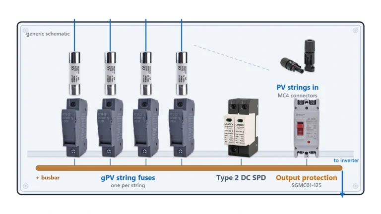
The previous example describes an individual PV source circuit or string fuse.
Array-output protection is different because several string currents are combined.
For a conventional NEC-based calculation, Littelfuse gives the PV output fuse relationship as:
Fuse rating ≥ 1.56 × combined string Isc
If four identical strings each have:
Isc = 11.2 A
their combined short-circuit current is:
4 × 11.2 A = 44.8 A
The preliminary OCPD calculation becomes:
1.56 × 44.8 A = 69.89 A
This does not automatically mean “install a 70 A fuse.”
The next available protective-device rating must still be checked against:
- output conductor ampacity;
- combiner-box ratings;
- busbar current rating;
- inverter input requirements;
- ambient temperature;
- applicable code rules;
- available standard fuse ratings.
The distinction is important:
String fuse sizing uses the individual string current.
Array-output fuse sizing uses the combined current entering that output circuit.
Solar Fuse Calculator: Minimum Inputs You Need
A useful solar fuse calculator needs more than solar-panel wattage.
At minimum, it should ask for:
| Input | Why It Is Needed |
|---|---|
| Module Isc | Starting value for current calculations |
| Module Voc | Starting value for voltage calculations |
| Maximum series fuse rating | Upper module protection limit |
| Modules per string | Determines string voltage |
| Parallel strings | Determines combined and reverse-current conditions |
| Minimum temperature | Determines maximum cold-weather voltage |
| Maximum fuse ambient temperature | Required for fuse derating |
| Cable ampacity | Upper protection limit |
| Fuse holder rating | Assembly compatibility |
A calculator that asks only:
Panel watts + system volts
is not sufficient for engineering-grade PV fuse selection.
What Size Fuse for a 100W, 200W or 400W Solar Panel?
There is no universal fuse size for a given solar-panel wattage.
For example, two 400 W modules might have:
Module A: higher voltage and lower current
Module B: lower voltage and higher current
Although both are rated 400 W, their Isc values can differ enough to require different protection calculations.
Therefore:
| Question | Correct Starting Point |
|---|---|
| Fuse for 100 W panel? | Check Isc and maximum series fuse rating |
| Fuse for 200 W panel? | Check Isc and maximum series fuse rating |
| Fuse for 400 W panel? | Check Isc and maximum series fuse rating |
| Fuse for multiple panels? | Also check series/parallel configuration |
Wattage is not a substitute for electrical current data.
Does 1.56 × Isc Apply to Every Solar Fuse?
No.
The 1.56 factor is widely used for conventional NEC-based PV source-circuit OCPD sizing because it combines two 125% factors.
It should not automatically be applied to:
- battery fuse sizing;
- inverter battery cables;
- charge-controller output circuits;
- arbitrary DC loads;
- automotive DC systems;
- every IEC-designed PV system.
Those circuits have different current sources and protection requirements.
This article specifically addresses PV source and array fuse sizing.
Battery-side protection should be calculated from the battery circuit, connected equipment and prospective fault current rather than from PV module Isc.
Solar Fuse Sizing Under IEC and NEC
PV projects are built under different regulatory frameworks.
For North American projects, the current edition is NFPA 70, National Electrical Code 2026, although the edition legally adopted in a particular jurisdiction may be older.
For international PV-array design, IEC 62548-1:2023+A1:2025 is the current IEC array-design standard.
Photovoltaic fuse-links themselves are covered by IEC 60269-6:2010+A1:2021, which applies to PV fuse-links for circuits up to 1500 V DC.
Do not mix individual equations from IEC and NEC methods without confirming that the resulting protection design complies with the standard governing the project.
For international OEM projects, the required design standard should therefore be identified before final fuse selection.
Common Solar Fuse Sizing Mistakes
Using Panel Wattage
Fuse size is based on current and protection requirements, not wattage alone.
Selecting Exactly 1.56 × Isc
The calculated result may not correspond to an available fuse size.
Select an appropriate standard rating and then recheck all upper limits.
Automatically Using the Maximum Series Fuse Rating
The maximum series fuse rating is an upper limit, not a recommended size.
Ignoring Cold-Weather Voltage
PV string Voc increases as module temperature decreases.
Fuse voltage rating must cover the maximum calculated system voltage.
Ignoring Temperature Derating
PV combiner boxes can operate at elevated internal temperatures.
Always check the fuse manufacturer’s temperature data.
Checking the Fuse but Not the Holder
Fuse and holder ratings must be coordinated.
Increasing Fuse Size to Stop Nuisance Operation
Repeated fuse operation can indicate:
- an incorrect design;
- abnormal current;
- high temperature;
- unsuitable holder;
- circuit fault.
Increasing ampere rating without checking the protection limits can defeat the purpose of the fuse.
Solar Fuse Sizing Checklist
Before finalizing a PV fuse, confirm all of the following:
| Check | Requirement |
|---|---|
| Module Isc | Obtained from actual module datasheet |
| Maximum circuit current | Calculated according to applicable standard |
| Minimum fuse current | Meets required OCPD calculation |
| Maximum series fuse rating | Selected fuse does not exceed it |
| Cable ampacity | Properly coordinated with fuse |
| String Voc | Calculated from modules in series |
| Cold-weather voltage | Below fuse DC voltage rating |
| gPV classification | Appropriate for PV protection |
| Breaking capacity | Adequate for available fault current |
| Temperature derating | Verified at actual ambient |
| Fuse holder | Correct current, voltage and dimensions |
| Applicable standard | IEC, NEC, UL or project requirement confirmed |
A reliable selection must pass every applicable check, not merely the current calculation.
Selecting a PV Fuse for an OEM or Solar Project
For an RFQ or technical quotation, provide the electrical information rather than requesting only an ampere value.
Useful information includes:
PV module model
→ Isc
→ Voc
→ maximum series fuse rating
→ modules per string
→ parallel strings
→ maximum system voltage
→ cable size
→ required fuse format
→ applicable standard or certification
This makes it possible to distinguish whether the project needs, for example, a particular 1000 V or 1500 V gPV fuse and compatible holder rather than selecting solely from the printed ampere rating.
For available PV protection configurations, see the UHCCY DC Fuse range.
Fuse selection should ultimately be verified against the actual PV module documentation, conductor design, fuse manufacturer’s technical data, system architecture and locally applicable electrical requirements.