Table of Contents
An MC4 extension cable extends the DC connection between a photovoltaic module or string and another part of the PV system.
The concept is simple, but choosing one correctly involves more than selecting a cable that is long enough.
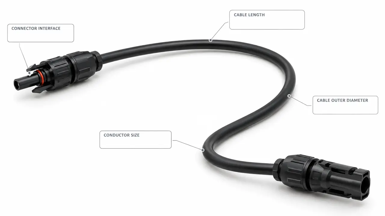
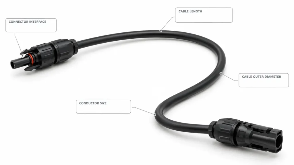
Cable length affects electrical resistance and voltage drop. Conductor size affects both resistance and current capability. The connector must match the cable as well as the connector system already installed.
A useful way to specify a solar panel extension cable is therefore:
Length + Conductor Size + Cable Type + Connector + Electrical Duty
rather than:
“I need a 20-foot MC4 cable.”
For available PV cable options, see Solar Cable. For connector configurations, see Solar Connector.
What Is an MC4 Extension Cable?
An MC4 extension cable is a length of photovoltaic cable terminated with complementary PV connector interfaces so an existing PV connection can reach a more distant connection point.
Typical applications include extending wiring between:
- PV modules and string wiring
- modules and charge controllers
- module strings and combiner boxes
- combiner boxes and other DC equipment
- PV arrays and inverter-side DC wiring
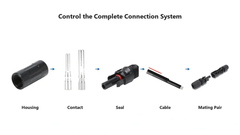
A finished extension assembly usually consists of:
PV cable + terminated contact + connector at End A + connector at End B
The connector and cable should therefore be treated as one assembly.
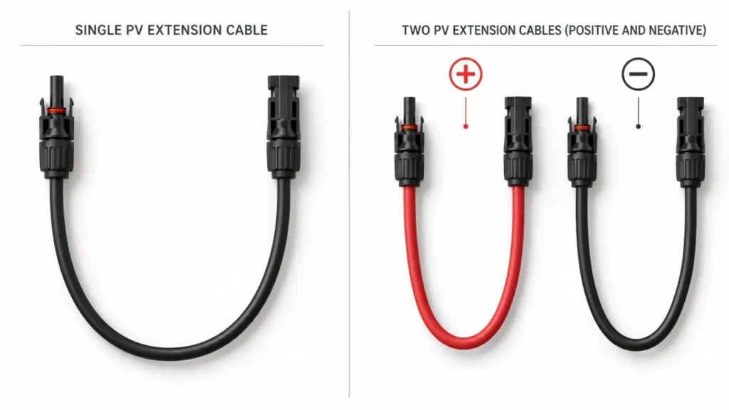
One Extension Cable Does Not Always Mean One Positive-and-Negative Pair
This causes more confusion than it should.
PV wiring normally uses separate single-core conductors for positive and negative DC paths.
An individual extension cable may therefore extend only one polarity.
A complete module-to-equipment extension can require:
one positive extension conductor
and:
one negative extension conductor.
Some sellers package these as a pair.
Others sell each conductor separately.
Before ordering, check whether the stated quantity refers to:
- one single-core extension cable
- one positive/negative pair
- one preassembled cable harness
Do not assume that “10 m solar extension cable” automatically means two 10 m conductors.
How Long Can an MC4 Extension Cable Be?
There is no universal maximum extension-cable length.
The usable length depends on the electrical system.
Important factors include:
- circuit current
- conductor cross-section
- conductor resistance
- total current path length
- acceptable voltage drop
- installation temperature
- cable installation method
This is why a table that says:
“10 AWG = maximum 30 ft”
without defining the system conditions is not a universal PV design rule.
The same cable can behave very differently in:
- a low-voltage, high-current system
- a high-voltage PV string carrying the same power at lower current
The cable length should be determined from the circuit rather than selected from length alone.
Why Cable Length Creates Voltage Drop
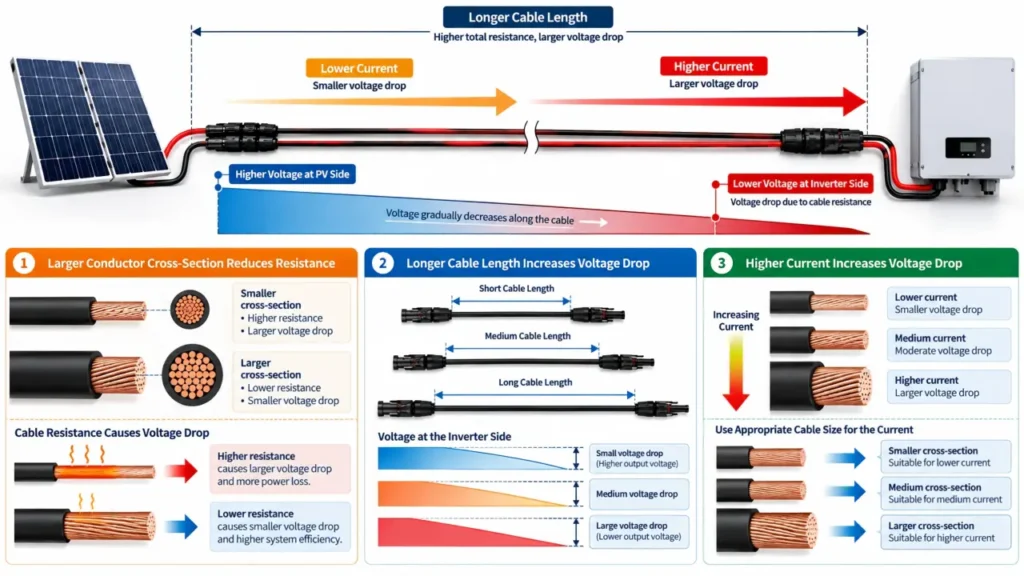
Every conductor has electrical resistance.
As current flows through that resistance, part of the circuit voltage is lost along the cable.
The basic relationship is:
Voltage Drop = Current × Circuit Resistance
or:
Vdrop = I × R
For a two-conductor DC circuit where the positive and negative paths have equal one-way length:
Vdrop ≈ 2 × L × I × Rₗ
where:
L = one-way cable length
I = circuit current
Rₗ = conductor resistance per unit length
The important relationship is straightforward:
longer cable → more resistance
higher current → more voltage drop
larger conductor → lower resistance
This is why cable length cannot be separated from cable size.
There Is No Universal “2% Rule” for Every Extension Cable
Online solar guides frequently recommend keeping voltage drop below a particular percentage.
A design target can be useful, but it should not be treated as a universal specification of the connector or cable.
Permitted or preferred voltage drop can depend on:
- project design criteria
- system voltage
- circuit location
- inverter requirements
- applicable installation standard
- economic design decisions
The better approach is:
- calculate the expected voltage drop
- express it as a percentage of the relevant circuit voltage
- compare it with the project’s design criteria
- increase conductor size if necessary
For PV array design, the current consolidated IEC 62548-1 covers areas including DC array wiring and cable requirements.
MC4 Extension Cable Size: 2.5, 4 or 6 mm²?
There is no single cable size that is correct for every extension.
Common PV conductor sizes include:
- 2.5 mm²
- 4 mm²
- 6 mm²
- larger sizes where system design requires them
The required cross-section depends primarily on:
current capability
and:
voltage-drop requirement.
A longer run does not automatically require a larger cable.
But if the original conductor size produces too much resistance or does not meet the required current-carrying capability under the installation conditions, increasing conductor cross-section can be necessary.
This is why an extension cable should not automatically copy the module lead size without checking the complete circuit.
Should the Extension Cable Be the Same Size as the Solar Panel Cable?
Using the same conductor size can be appropriate when it satisfies the complete design requirements.
But:
“match the existing cable size” is a starting point, not a universal engineering rule.
For example, a short module lead and a much longer extension run have different total resistances even when both use the same conductor cross-section.
The longer extension may justify a larger conductor to control voltage drop.
However, increasing cable size creates another question:
Will the connector accept that conductor and cable diameter?
The cable and connector therefore have to be selected together.
Conductor Cross-Section and Cable OD Must Both Match
An extension cable needs to fit its connector in two different ways.
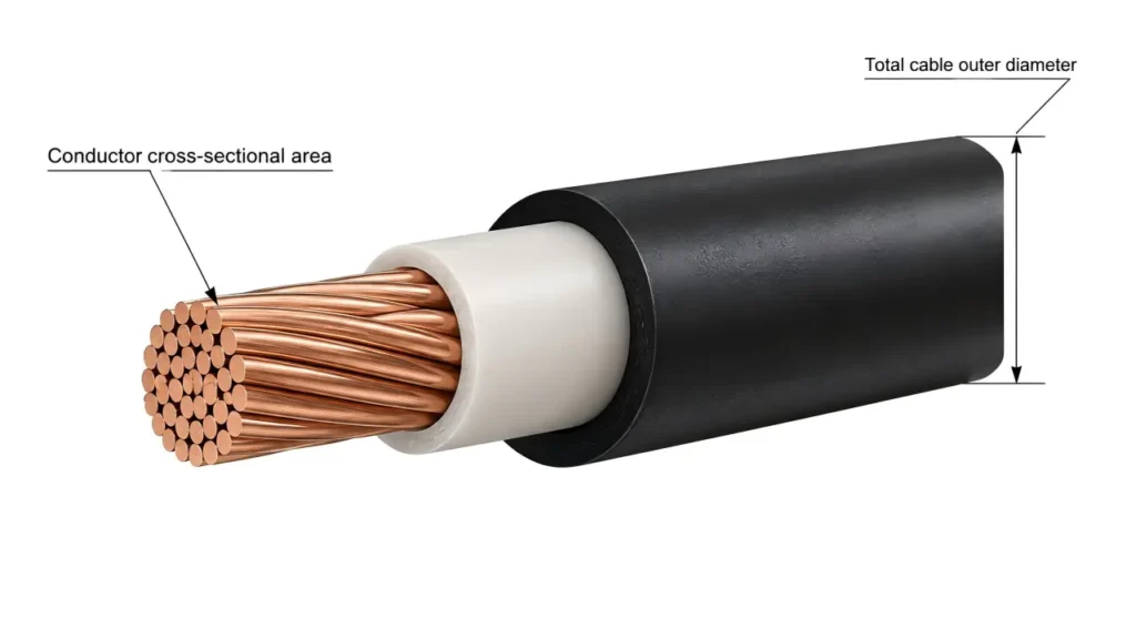
Conductor Cross-Section
This determines whether the metal contact is designed for the conductor.
Typical values are specified in:
mm²
or, for North American documentation:
AWG.
Cable Outer Diameter
This determines whether the connector’s cable gland and sealing system can correctly grip the cable jacket.
Two cables can both have a:
4 mm² conductor
while having different outer diameters.
Therefore:
4 mm² cable compatibility does not automatically prove connector sealing compatibility.
Always check both values.
For a deeper explanation, see MC4 Connector Specifications.
Cable Size and Connector Size Are Not Independent
One common purchasing mistake is selecting:
6 mm² extension cable
and:
a connector described as suitable for 6 mm²
without checking anything else.
The metal contact must be suitable for the conductor.
The sealing system must be suitable for the cable OD.
The connector current and voltage ratings must also be suitable for the circuit.
A complete extension assembly therefore needs:
Cable conductor → Correct crimp contact → Correct connector housing → Correct mating connector
This is the same system principle used for field termination.
See How to Crimp MC4 Connectors if the extension cable will be assembled in the field.
What Cable Should Be Used for a Solar Panel Extension?
A permanent outdoor PV extension should use cable suitable for its intended photovoltaic DC installation rather than ordinary household extension wire.
The applicable cable requirements depend on the market and installation.
For IEC-oriented photovoltaic systems, IEC 62930 covers single-core cables intended for the DC side of photovoltaic systems with rated voltage up to 1.5 kV DC.
The official standard can be referenced at IEC 62930 — Electric cables for photovoltaic systems.
Cable selection may also need to consider:
- rated DC voltage
- conductor material
- insulation system
- UV exposure
- temperature
- moisture
- routing
- mechanical protection
- applicable regional requirements
Do not infer all of these properties from the words “solar cable.”
Verify the actual cable specification.
1000 V and 1500 V Extension Cables
The extension assembly must be suitable for the voltage class of the PV circuit.
A 1500 V DC system requires every relevant component in the connection path to have an appropriate voltage rating.
That includes:
cable
connector
contact system
and any downstream components.
A cable marked for 1500 V does not automatically make a connector attached to it suitable for 1500 V.
Likewise, a 1500 V connector does not increase the rating of an unsuitable cable.
The complete assembly is limited by its applicable components and documented ratings.
Does a Longer Extension Cable Reduce Solar Power?
A longer cable does not inherently reduce the power produced by the PV module itself.
It increases conductor resistance.
The resulting electrical loss is approximately:
Ploss = I² × R
This is important because cable loss increases with the square of current.
Therefore high-current cable runs are more sensitive to resistance than lower-current runs.
This also helps explain why a PV array operating at a higher DC voltage can transmit the same power at a lower current, reducing conductor losses for a given resistance.
The practical conclusion is not:
“Always use higher voltage.”
It is:
Evaluate voltage, current, cable resistance and equipment limits together.
Extension Cable Length Should Be Measured as the Electrical Path
Another common mistake is measuring only the physical distance between the module and equipment.
Imagine the equipment is 20 m away.
The electrical current may need to travel:
20 m outward and 20 m back through the complementary conductor.
The relevant resistance calculation therefore considers the complete current path.
This is why voltage-drop calculations often include twice the one-way distance when equal positive and negative conductor lengths are assumed.
If the conductor routes are different lengths, use the actual total circuit length instead.
MC4 Extension Cable Male and Female Connectors
A typical PV extension assembly has complementary connector interfaces so it can be inserted into an existing connection path.
However, do not use connector gender alone to determine polarity.
The connector attached to a positive extension conductor must mate with the connector already present on the positive circuit.
That necessarily means the interfaces on opposite sides of the connection are complementary.
So:
connector interface ≠ electrical polarity.
This subject is explained in detail in MC4 Male vs Female Connectors.
Do Not Reverse Polarity by Making the Extension Cable
If you fabricate extension cables yourself, verify:
- connector orientation
- cable identification
- conductor polarity
- mating counterpart
before installation.
A cable can be mechanically assembled perfectly while still being electrically wrong.
After termination, confirm that:
positive remains positive through the completed cable path
and:
negative remains negative.
The MC4 Connector Wiring Guide covers PV polarity and series/parallel wiring in more detail.
MC4 Extension Cable vs Adapter Cable
These are not the same product.
Extension Cable
Maintains the same PV connection system while increasing cable length.
Conceptually:
PV connector system → PV cable → same connection system
Adapter Cable
Transitions between different connector interfaces.
Examples in the wider market include:
PV connector → portable-power-station input
PV connector → ring terminal
PV connector → other DC interface
An adapter adds another compatibility question because the electrical requirements of both systems need to be considered.
For UHCCY’s current B2B solar-component strategy, standard PV cable and connector assemblies are more relevant than consumer portable-power-station adapters.
Adding Extension Cable Does Not Mean Adding Panels
An extension cable changes the physical cable route.
It does not change the array topology by itself.
It does not:
- add PV modules
- increase series voltage
- increase parallel current
- create a branch connection
This distinction is useful because extension cables, branch connectors and series wiring are sometimes mixed together in product listings.
If the objective is to combine several PV sources, see the MC4 Y Connector Guide.
Can You Join Two Extension Cables Together?
Mechanically, compatible extension assemblies can potentially be connected end to end.
But repeatedly adding extensions is not automatically good system design.
Every additional connector pair introduces:
- another contact interface
- another sealing interface
- another mechanical connection
- another potential failure point
If a permanent installation needs a substantially longer run, one correctly sized cable assembly is generally cleaner than creating a chain of unnecessary intermediate connections.
The exact installation approach should still follow the equipment and project requirements.
Connector Compatibility Still Matters
An extension cable is only useful if its connectors are valid mating counterparts for the equipment already installed.
Do not assume compatibility because:
- both products are black
- both are described as MC4-style
- the housings appear to fit
- the locking tabs click
Physical fit does not prove documented compatibility.
For mixed connector systems, see MC4 Connector Compatibility.
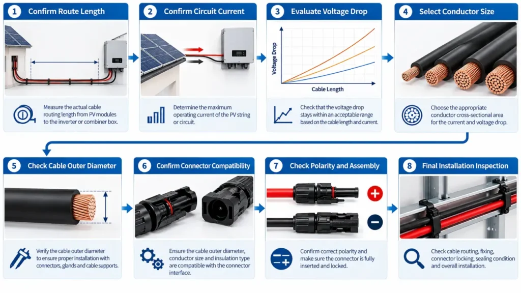
How to Choose an MC4 Extension Cable
A useful selection process is:
1. Determine the Required Route Length
Measure the real installation route rather than straight-line distance.
Allow for:
- cable routing
- service loops where required
- bend radius
- equipment access
- cable support
Avoid unnecessary excess length.
2. Determine Circuit Current
Use the actual PV circuit design.
A single module lead, series string and combined parallel output can carry different currents.
3. Select Cable Cross-Section
Check:
- current-carrying requirement
- voltage drop
- installation environment
Do not choose cable size from connector appearance alone.
4. Verify Cable Voltage Rating
Make sure the cable is suitable for the PV system voltage and intended installation.
5. Verify Connector/Cable Compatibility
Check both:
conductor cross-section
and:
cable OD.
6. Verify the Mating Connector
Identify the manufacturer and connector system already installed.
Do not rely only on the phrase “MC4 compatible.”
7. Confirm Polarity
Verify the completed cable orientation before commissioning.
8. Check the Complete Assembly
Inspect:
- crimp
- contact retention
- gland
- connector locking
- cable support
Common MC4 Extension Cable Mistakes
Choosing by Length Only
A 20 m cable and a 5 m cable of the same cross-section do not have the same total resistance.
Assuming AWG or mm² Alone Determines Compatibility
The connector also depends on cable outer diameter and contact design.
Buying One Cable When Two Conductors Are Required
Check whether the product is sold individually or as a positive/negative pair.
Using a Larger Cable Without Checking the Connector
Increasing conductor size may solve one voltage-drop problem while creating an incompatible termination.
Treating “MC4 Compatible” as a Complete Specification
Verify the actual mating connector.
Ignoring Polarity After Custom Assembly
Connector orientation should not be assumed to prove electrical polarity.
Using Ordinary Wire for Permanent Outdoor PV Wiring
Cable suitability should match the actual photovoltaic environment and applicable requirements.
Adding Multiple Short Extensions Instead of Designing the Run
Unnecessary connector interfaces add complexity without improving the electrical design.
Extension Cable Procurement for B2B Buyers
A professional RFQ should specify more than:
“Need 10 m MC4 extension cable.”
A useful specification includes:
| Requirement | What to specify |
|---|---|
| Finished length | Required cable length |
| Quantity | Individual cable or positive/negative pair |
| Conductor | 2.5 / 4 / 6 mm² or project requirement |
| Cable OD | Required or actual cable diameter |
| Cable standard | Applicable PV cable requirement |
| Rated voltage | Project DC voltage |
| Current duty | Circuit requirement |
| End A | Exact connector/interface |
| End B | Exact connector/interface |
| Mating counterpart | Existing module/equipment connector |
| Cable color | Black / red where required |
| Marking | Standard or OEM marking |
| Packaging | Coil, bag, set or project packaging |
| Documentation | Cable and connector technical data |
This prevents suppliers from quoting assemblies that have the same length but different:
- conductor size
- cable construction
- connectors
- ratings
- certification basis
For bulk and OEM projects, the extension cable should be treated as a defined cable assembly, not just a length of wire.
UHCCY Solar Cable and Solar Connector can be specified together according to the required project configuration.
Key Takeaway
An MC4 extension cable is mechanically simple but electrically dependent on the complete PV circuit.
The main selection logic is:
Length → Current → Voltage Drop → Cable Cross-Section → Cable OD → Connector → Polarity and Mating Compatibility
Remember:
- There is no universal maximum MC4 extension-cable length.
- Longer cable increases resistance and voltage drop.
- Higher current increases both voltage drop and cable loss.
- Larger conductor cross-section reduces resistance but must still fit the connector.
- Cable conductor size and cable outer diameter are separate specifications.
- A complete PV extension normally needs both positive and negative current paths.
- Connector gender should not be used alone to identify polarity.
- An extension cable does not change series or parallel topology by itself.
- Avoid unnecessary chains of extension connectors in permanent wiring.
- For B2B purchasing, specify the complete cable assembly rather than only its length.
The correct question is therefore not:
“How long can an MC4 cable be?”
It is:
“What cable size and connector assembly will carry this PV circuit over the required distance with acceptable electrical performance?”