Table of Contents
An MC4 Y connector is commonly used to combine photovoltaic conductors when solar modules or strings are connected in parallel.
The mechanical idea is simple: two or more connector inputs become one output.
The electrical consequence is more important:
the currents from the parallel branches combine on the output side.
That means a branch connector should not be selected only by counting how many sockets it has. The output contact, cable, downstream connector and protection scheme must all be suitable for the combined current.
The following values are hypothetical examples used only to illustrate current addition in parallel circuits. They are not connector ratings. The actual rated current of a Y or branch connector must always be taken from the datasheet for the exact connector model.
For other connector configurations, see MC4 Connector Types Explained.
What Is an MC4 Y Connector?
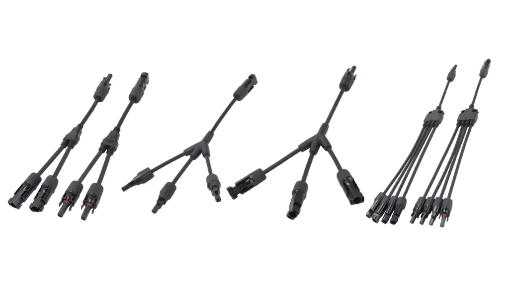
An MC4 Y connector is a branch connection used to combine two photovoltaic conductors into a single output or, depending on circuit direction, distribute one conductor into two branches.
In PV applications, the most common use is parallel combining.
For two modules or strings:
Positive branch 1 + Positive branch 2 → one positive output
and:
Negative branch 1 + Negative branch 2 → one negative output
This requires a complementary pair of branch connectors—one for the positive conductors and one for the negative conductors.
The result is not simply a mechanical cable splitter.
It creates a new electrical node at which current from multiple PV sources can combine.
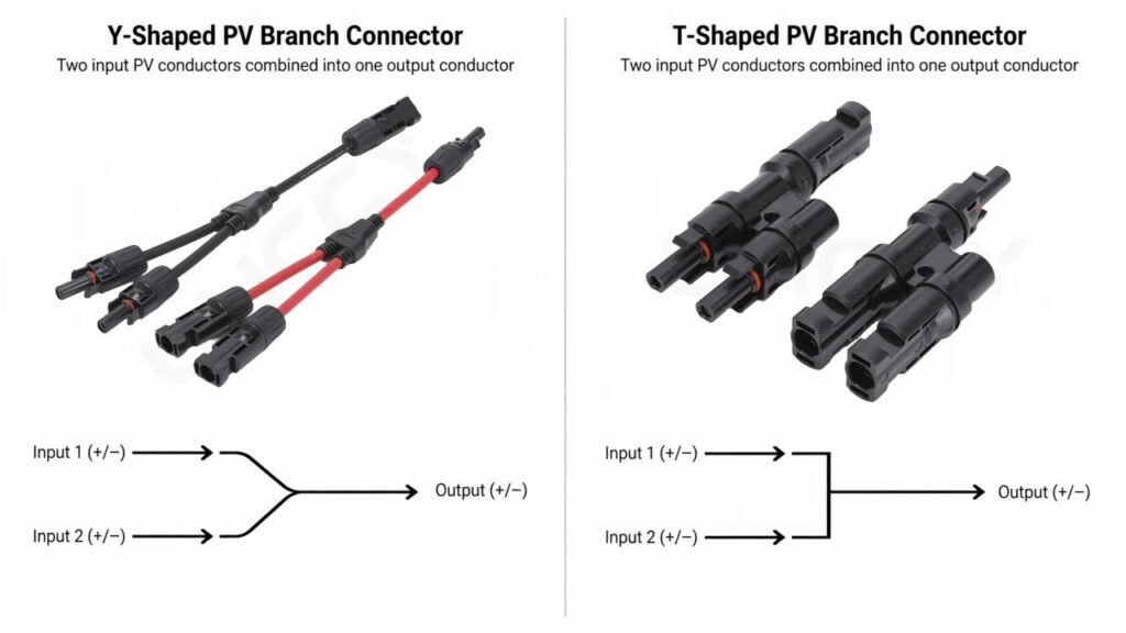
Y Connector, Branch Connector and Splitter: Are They the Same?
These terms are often used interchangeably in online product listings:
- MC4 Y connector
- MC4 branch connector
- solar Y connector
- PV branch connector
- solar splitter connector
- parallel connector
They often describe the same basic function, but the terminology is not technically identical.
Branch connector describes the electrical function.
Y connector describes a common physical shape.
Splitter is a broad commercial term and does not explain the electrical rating or intended application.
For technical documentation and purchasing, PV branch connector is usually the more useful generic description because it focuses on what the component does rather than what its housing looks like.
MC4 Y Connector Wiring: What Happens Electrically?
The key rule for parallel PV wiring is:
Voltage remains approximately the voltage of one matched branch, while current adds.
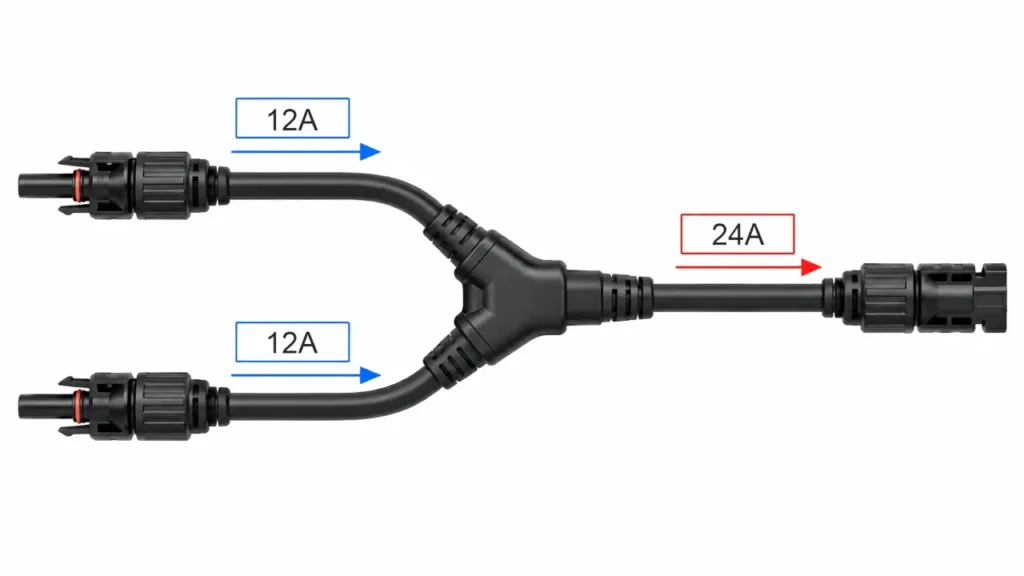
Consider two identical modules.
Each module operates at approximately:
Vmp = 40 V
Imp = 12 A
When connected in parallel:
Vmp ≈ 40 V
while:
Imp ≈ 12 A + 12 A = 24 A
The branch connector output may therefore need to carry approximately twice the current of either individual module lead.
With three parallel branches:
8 A + 8 A + 8 A ≈ 24 A
With four:
6 A × 4 ≈ 24 A
These numbers are only an illustrative example. Actual system design must use the electrical characteristics of the modules being installed.
The important relationship is:
more parallel branches → more current on the combined side.
For the complete series/parallel relationship, see the MC4 Connector Wiring Guide.
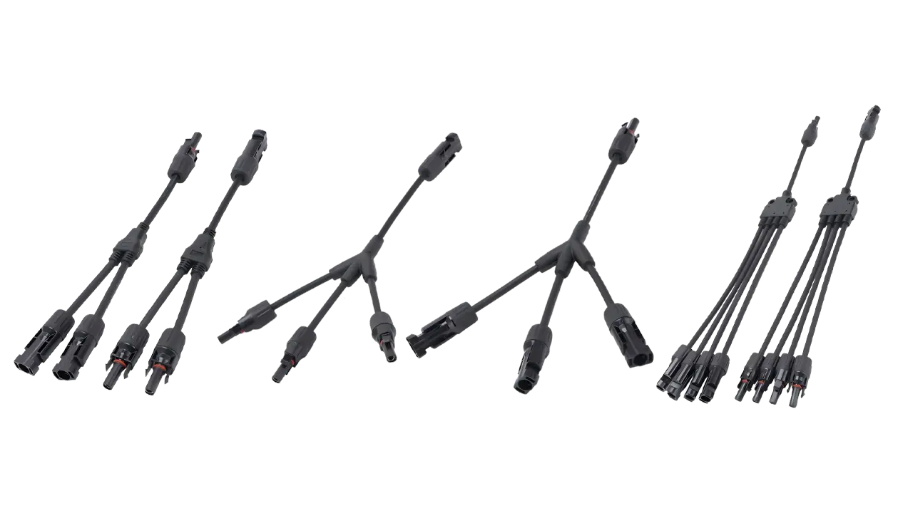
2-to-1 MC4 Branch Connector
A 2-to-1 branch connector combines two PV inputs into one output.
It is the simplest and most common branch configuration.
Typical uses include:
- two modules connected in parallel
- two matched PV strings combined before downstream equipment
- small off-grid arrays
- equipment requiring one pair of PV input conductors from two parallel sources
The connector pair normally performs:
2 positive inputs → 1 positive output
and:
2 negative inputs → 1 negative output
The Output Side Is the Critical Part
Suppose each branch carries 12 A.
The output side may carry approximately:
24 A
under normal operating conditions.
Therefore, the output connection must be evaluated for that combined current.
This includes:
- branch connector contact
- output cable
- downstream connector
- equipment terminal
- conductor ampacity
- protection requirements
A connector rated adequately for one 12 A branch is not automatically adequate for the 24 A combined path.
3-to-1 Branch Connectors
A 3-to-1 connector combines three parallel sources.
Using identical 13 A branches as an illustrative example:
8 A × 3 ≈ 24 A
The advantage is mechanical simplicity: three inputs can be consolidated into one output without cascading multiple 2-to-1 adapters.
But the electrical requirements become more important as the number of branches increases.
Check:
- maximum operating current
- short-circuit current
- connector rating
- combined-output cable size
- equipment input rating
- overcurrent protection requirements
A 3-to-1 connector should therefore not be viewed as simply:
“the same connector with one extra port.”
The combined circuit is different.
4-to-1 Branch Connectors
A 4-to-1 branch connector combines four parallel conductors into one output.
This can simplify wiring in compact systems where four matched branches need to enter one downstream circuit.
However, four parallel sources can create a substantially higher combined current.
For four 13 A branches:
6 A × 4 ≈ 24 A
Again, this is only an example.
The important question becomes:
Can every component after the combining point carry and protect the resulting current?
That includes components that may be physically far away from the branch connector.
For example:
branch connector → output cable → connector → disconnect → inverter / controller input
The entire path matters.
2-to-1 vs 3-to-1 vs 4-to-1
The correct number of branches should follow the PV circuit design.
| Configuration | Inputs | Main use | Key consideration |
|---|---|---|---|
| 2-to-1 | 2 | Combine two modules or strings | Combined current approximately doubles |
| 3-to-1 | 3 | Three matched parallel sources | Output current becomes more significant |
| 4-to-1 | 4 | Four matched parallel sources | Cable/protection design becomes increasingly important |
Do not choose a 4-to-1 connector merely because it offers extra unused ports.
Use the configuration required by the actual array design and connector manufacturer’s instructions.
Unused connection interfaces should not be treated casually in an outdoor PV environment.
Y Connector vs T Connector
Users often search for whether a Y connector or T connector is better.
There is no universal electrical answer.
The letters primarily describe physical geometry.
A Y-shaped 2-to-1 connector and a T-shaped 2-to-1 connector can perform the same parallel combining function.
What can differ is:
- internal contact design
- cable routing
- installation clearance
- body dimensions
- current rating
- sealing method
- mechanical loading
- manufacturing method
Therefore:
Y vs T is mainly a mechanical-design question until the actual technical specifications show otherwise.
Do not assume that one housing shape inherently carries more current or lasts longer than the other.
For a broader classification of PV connector functions, see MC4 Connector Types Explained.
Does an MC4 Y Connector Increase Voltage?
No—not when it is being used to combine matched PV sources in parallel.
Parallel wiring mainly combines current.
Voltage remains approximately equal to the voltage of one branch.
For example:
Two matched 40 V modules in parallel:
≈ 40 V
not:
≈ 80 V
The current increases instead.
If your design requires higher voltage, modules are normally connected in series, not simply combined through a Y branch.
This is an important distinction because connecting modules in the wrong topology can move the array outside the inverter or MPPT controller’s permitted operating range.
Does an MC4 Y Connector Increase Current?
The connector does not create additional electrical power.
What it does is combine the current already being produced by the parallel branches.
For matched branches:
Icombined ≈ I1 + I2 + I3 + …
This is why branch connector selection should always begin with the combined circuit current rather than the current of one individual module.
Imp and Isc: Which Current Matters?
PV modules normally specify at least two current values:
Imp — current at maximum power
and:
Isc — short-circuit current
Imp helps describe normal operating current.
Isc is important when evaluating maximum circuit current and protection requirements.
A branch connector should not be selected merely by multiplying module Imp and checking whether the result is below a marketing current rating printed on a product page.
Actual PV circuit design may require additional factors according to the applicable standard or electrical code.
The correct process is:
- determine the module electrical ratings
- determine the number of parallel branches
- calculate the applicable circuit current
- verify connector and conductor ratings
- evaluate required overcurrent protection
This is why a branch connector should be treated as part of the electrical design, not as an accessory added afterward.
Branch Connectors and Overcurrent Protection
Parallel PV strings introduce an additional issue:
one string can potentially receive current from the other parallel strings during certain faults.
This does not mean every branch connection automatically requires an inline fuse.
The requirement depends on factors such as:
- number of parallel sources
- maximum available current
- module maximum series fuse rating
- conductor ampacity
- downstream equipment
- applicable installation rules
For a small parallel arrangement, the available fault current may remain within the permitted equipment limits.
As the number of parallel strings increases, string-level protection becomes more likely to be required.
The practical rule is:
do not decide whether a fuse is required from the shape of the branch connector.
Evaluate the actual circuit.
For a fuller explanation, see the MC4 Connector Wiring Guide.
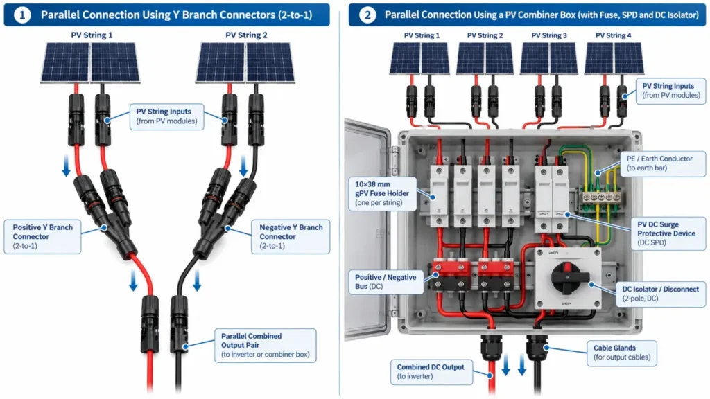
Branch Connector vs Combiner Box
Both devices can be used when parallel PV circuits need to come together, but they solve different levels of the problem.
Use a Branch Connector When
A branch connector can be appropriate where:
- only a small number of matched PV branches need combining
- the combined current stays within the complete connector/cable path ratings
- required protection is provided elsewhere or is not required for that circuit
- a compact in-line connection is desirable
- monitoring and individual string isolation are not needed
Consider a Combiner Box When
A PV combiner box becomes more useful where the installation requires:
- multiple parallel strings
- individual string fuses
- surge protective devices
- disconnecting devices
- monitoring
- organized cable termination
- transition to a larger output conductor
- easier inspection and maintenance
This is not a fixed rule such as:
“two strings = Y connector, three strings = combiner box.”
The correct choice depends on the electrical and maintenance requirements of the project.
Can You Daisy-Chain Multiple Y Connectors?
Physically, multiple 2-to-1 branch connectors can sometimes be cascaded to combine more circuits.
For example:
two inputs → one branch connector
then:
that output + another branch → another connector
But this is not automatically equivalent to using a properly specified multi-branch connector or combiner.
Cascading creates:
- additional contact interfaces
- additional potential resistance points
- more mechanical connections
- more sealing interfaces
- more difficult current-path analysis
The final output still has to carry the total combined current.
For repeat installations, using a connector designed for the required number of branches—or moving to a combiner box—can produce a cleaner system.
Do Not Select a Branch Connector Only by “30A / 50A / 60A”
Current labels on PV connectors need context.
A claimed current rating may depend on:
- exact contact design
- conductor cross-section
- ambient conditions
- certification basis
- complete mated pair
For example, a branch connector with several 4 mm² inputs does not automatically mean that a 4 mm² output cable is appropriate for every possible combined current.
Always distinguish:
input cable compatibility
from:
combined-output current requirement.
For a detailed explanation of connector ratings and cable dimensions, see MC4 Connector Specifications.
Cable Size After the Branch Connector
The cable before and after a branch connection can serve different electrical duties.
Before the branch:
each cable carries one branch current.
After the branch:
one cable carries the combined current.
This may mean the downstream conductor requires a different cross-section.
The decision depends on:
- combined design current
- cable ampacity
- installation temperature
- cable routing
- voltage drop
- applicable standards
This is especially important for long cable runs.
Higher current creates greater resistive voltage drop and conductor heating for the same cable resistance.
A compact branch connector may therefore be physically capable of combining several sources while the downstream cable becomes the limiting component.
Voltage Drop After Parallel Combining
For a DC conductor:
Voltage drop ≈ Current × Circuit resistance
When current increases after several parallel branches are combined, voltage drop increases unless resistance is reduced.
Resistance can be reduced by:
- increasing conductor cross-section
- shortening the cable run
- using a suitable conductor material and construction
- maintaining low-resistance terminations
This is one reason array topology and cable routing should be considered together.
Branch connectors are small components, but their location can affect the current carried over the longest downstream cable run.
Male/Female Branch Connector Terminology
Branch connector product names can become confusing because sellers may use codes such as:
MMF
or:
FFM
to describe the number of male and female interfaces.
The exact interpretation can also depend on whether the seller is describing:
- plastic connector housing
- metal contact
- plug/socket interface
For professional purchasing, do not rely only on a three-letter gender description.
Specify:
- exact connector model
- number of input interfaces
- output interface
- intended mating counterpart
- polarity/orientation of the finished assembly
The distinction between connector gender and electrical polarity is explained in MC4 Male vs Female Connectors.
Can Different Branch Connector Brands Be Mixed?
Do not assume they can.
The same compatibility principles apply to branch connectors as to standard inline connectors.
Even if a branch connector physically mates with the module connector, verify:
- manufacturer
- connector series
- mating documentation
- current rating
- contact system
- applicable certification
A branch connector introduces several mating interfaces rather than one, so undocumented cross-mating can multiply the number of mixed connection points in the array.
See MC4 Connector Compatibility for the full cross-mating discussion.
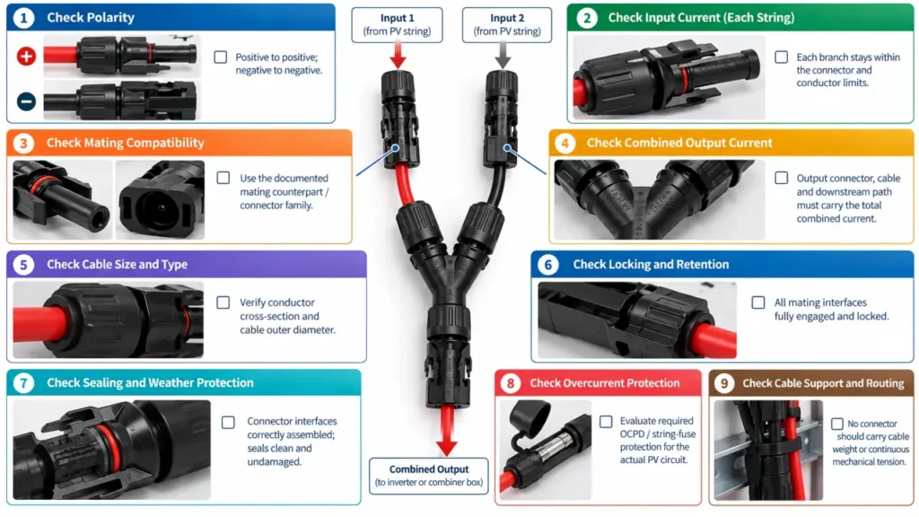
Field Installation Checks
Before commissioning a branch connection, confirm:
| Check | What to verify |
|---|---|
| Branch count | Correct 2-to-1, 3-to-1 or 4-to-1 configuration |
| Module/string match | Parallel sources are electrically suitable to combine |
| Polarity | Positive-to-positive and negative-to-negative |
| Input current | Individual branches within connector limits |
| Combined current | Output path suitable for total current |
| Cable | Correct conductor cross-section and OD |
| Connector family | Documented mating counterpart |
| Locking | All interfaces fully engaged |
| Sealing | Correctly assembled connector interfaces |
| Cable support | No connector carrying cable weight or tension |
| Protection | OCPD requirements evaluated |
| Downstream equipment | Voltage/current within input limits |
A Better Way to Specify Branch Connectors for Purchasing
For B2B procurement, avoid requests such as:
“Quote MC4 Y connector.”
That still leaves too many variables.
A more useful RFQ includes:
Configuration: 2-to-1 / 3-to-1 / 4-to-1
System voltage: required DC voltage class
Input conductor: required mm²
Input cable OD: actual cable diameter
Maximum combined current: project requirement
Output cable: required conductor size
Mating connector: exact manufacturer/model where applicable
Protection design: fuse / combiner arrangement if relevant
Certification requirement: project/market specific
Lead length: if using cable-type Y splitters
Marking / OEM requirement: if applicable
This makes quotations from different suppliers much easier to compare.
For available UHCCY PV connection configurations, start with the Solar Connector category.
Fixed Y Connector vs Cable Y-Splitter
Branch connectors are available in more than one mechanical form.
Fixed-Body Branch Connector
Inputs and output are integrated into a compact molded body.
Advantages can include:
- compact installation
- fewer external cable sections
- simple arrangement
Cable Y-Splitter
The branch body uses short cable leads between connector interfaces.
This can provide:
- more flexible cable routing
- reduced mechanical crowding
- easier positioning in some installations
Neither design is universally better.
The correct choice depends on:
- available installation space
- mechanical support
- bend radius
- current rating
- cable specification
- environmental requirements
Stäubli, for example, currently offers both branch connector and Y-splitter configurations for parallel and series-parallel PV applications. The exact ratings and intended mating systems remain product-specific.
Key Takeaway
An MC4 Y connector is easy to understand mechanically but easy to underestimate electrically.
The main principle is:
The inputs carry individual branch currents. The output carries their combined current.
That leads to several practical rules:
- Use branch connectors for parallel—not series—combining.
- Select the connector by combined output current, not one-module current alone.
- 2-to-1, 3-to-1 and 4-to-1 configurations create increasingly higher combined current.
- Y and T mainly describe physical geometry, not electrical performance.
- Check both connector rating and downstream cable ampacity.
- Parallel circuits require an overcurrent-protection assessment.
- Do not assume every additional parallel string should simply be added with another Y connector.
- Use a combiner box when the project needs protection, monitoring, switching or organized multi-string termination.
- Verify mating compatibility rather than relying on “MC4 compatible” marketing language.
- For purchasing, specify the complete branch configuration instead of only asking for a Y connector.
The branch connector is not merely a cable splitter. It is the point where the electrical duty of the PV circuit changes.