Table of Contents
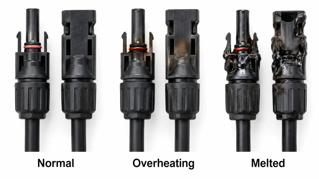
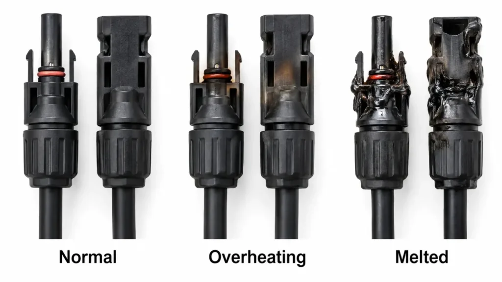
MC4 connector failure rarely begins with melted plastic.
The visible damage is usually the final stage of a problem that started earlier at an electrical or mechanical interface: a poor crimp, incomplete mating, incompatible contacts, moisture ingress, excessive current, cable strain or another condition that increases resistance or destabilizes the connection.
The useful question is therefore not:
“Why did the plastic melt?”
It is:
“Where did the connection begin to degrade, and why?”
This guide explains how PV connector failures develop, what different damage locations can tell you, and what installers and buyers can do to reduce the risk.
MC4 is a protected trademark of Stäubli. UHCCY uses Solar Connector and PV Connector for its own products.
For the broader connector system and ratings, see Solar Connector and MC4 Connector Specifications.
What Causes MC4 Connector Failure?
Most serious PV connector failures can be traced to one or more of six areas:
- poor conductor-to-contact termination
- incomplete or unstable contact engagement
- cross-mating or incompatible components
- sealing failure, contamination or corrosion
- current and thermal conditions beyond the connection’s capability
- mechanical stress or installation damage
These causes can interact.
For example:
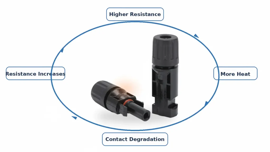
poor crimp → higher resistance → localized heating → thermal cycling → further degradation → even higher resistance
or:
incorrect cable OD → poor seal → moisture ingress → corrosion → higher contact resistance → heating
The failed housing seen during inspection may therefore be several steps removed from the original cause.
Why High Resistance Turns Into Heat
Every electrical connection has some resistance.
In a correctly designed and assembled connector, that resistance is low enough for the connection to carry its rated current without excessive temperature rise.
If local resistance increases, heat generation increases according to:
P = I²R
where:
P = power converted to heat
I = current
R = electrical resistance
The important part is the square on current.
If resistance remains the same but current doubles, resistive heating increases by approximately four times.
This does not mean that current alone causes connector failure.
It means that a small resistance defect becomes much more significant as operating current increases.
That is one reason a marginal termination may appear acceptable at low power and become much hotter during periods of high solar production.
Read the Failure Location Before Blaming the Connector
Where the damage appears can provide useful clues.
It does not prove the root cause, but it helps decide what should be investigated first.
| Damage location | Possible issue to investigate |
|---|---|
| Near cable entry / crimp | Poor crimp, damaged strands, wrong contact or conductor |
| Mating interface | Partial mating, contact damage, contamination or cross-mating |
| Cable gland / seal | Incorrect cable OD, loose gland, seal damage or moisture ingress |
| Locking area | Incomplete engagement, mechanical damage or excessive cable load |
| Entire connector unusually hot | Current loading, contact resistance, environment or multiple contributing factors |
| Corroded contact | Moisture ingress, contamination or incompatible mating system |
This is more useful than assuming every melted PV connector has the same cause.
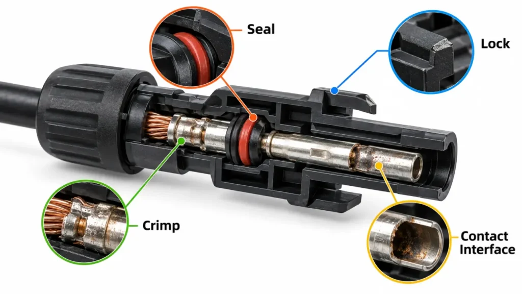
A connector should be treated as several interfaces:
Cable → Crimp → Contact → Mating Interface → Seal → Housing
Finding where the damage is concentrated helps narrow the investigation.
Crimp and Termination Problems
The conductor-to-contact crimp is one of the most important electrical interfaces inside a field-assembled PV connector.
Problems can include:
- wrong contact for the conductor
- wrong crimp die
- incomplete crimping cycle
- damaged conductor strands
- insulation trapped in the conductor crimp
- insufficient conductor insertion
- over-compressed or deformed contact
- unsuitable field tooling
A poor crimp can reduce the effective conductive area and increase local resistance.
The problem may be hidden after the contact is inserted into the housing.
This is why a connector can look completely normal from the outside while operating at an abnormal temperature internally.
For the termination process, see How to Crimp MC4 Connectors.
For tool selection, see MC4 Crimping Tool Guide.
Incomplete Mating and Contact Engagement
A connector that appears joined is not necessarily fully seated.
The internal pin/socket interface needs sufficient engagement while the external locking mechanism needs to reach its intended position.
Problems can arise from:
- contact not fully seated in the housing
- contact pushed backward during mating
- housing not fully locked
- damaged retention feature
- incorrect component combination
- debris blocking full engagement
This area has received increasing attention in field research.
A 2025 Sandia-led study examined 6,276 harvested rooftop PV connectors from U.S. installations and found that common installation issues included loose nuts and improperly seated connectors. The study also identified contact engagement length as an important variable and found a relationship between higher operating current, resistance and failure occurrence.
The open-access research is available here: Rapid characterization and failure analysis of 6276 rooftop-harvested photovoltaic connectors.
This is useful because it shows that connector reliability is not only a laboratory materials problem.
Installation geometry matters in the field.
Cross-Mating and Mixed Connector Systems
Two connector halves can physically fit while still not forming a verified mating system.
Differences can exist in:
- pin/socket geometry
- contact engagement depth
- spring pressure
- plating
- dimensional tolerances
- locking position
- sealing interface
If the internal contacts do not mate as intended, effective contact area or contact pressure may be reduced.
That can increase resistance.
Cross-mating can also compromise environmental sealing, allowing moisture to contribute to longer-term degradation.
Therefore:
Physical fit is not proof of electrical compatibility.
For the complete issue, see MC4 Connector Compatibility.
Cable OD, Sealing, Moisture and Corrosion
The cable gland is not only a mechanical part.
It also helps maintain the connector’s environmental protection.
A common mistake is checking only:
4 mm² / 6 mm² conductor size
while ignoring:
cable outside diameter.
These are different specifications.
A cable can have the correct conductor cross-section while being too small or too large for the connector’s sealing range.
Possible consequences include:
incorrect seal compression → moisture ingress → corrosion → increased resistance
Other sealing problems can come from:
- damaged O-rings or seals
- incorrectly assembled gland components
- loose cable gland nuts
- cracked housings
- connector contamination before mating
- open connectors left exposed during installation
Once moisture and corrosion reach the conductive interface, simply drying the outside of the housing does not restore the original contact condition.
For cable OD and sealing requirements, see MC4 Connector Specifications.
Current, Temperature and Thermal Margin
A connector’s current rating should not be treated as an isolated number.
The actual operating temperature depends on several conditions at the same time:
Circuit current + Contact resistance + Ambient temperature + Solar heating + Cable size + Installation environment
A connector operating outdoors above a hot roof has a different thermal environment from the same connector operating in free air at a lower ambient temperature.
Parallel branch circuits also need particular attention because the common side can carry current from several branches.
For branch applications, see MC4 Y Connector Guide.
Do Not Use One Universal “Safe Connector Temperature”
A single absolute temperature without context is not always a good diagnostic rule.
A connector measured at a certain temperature on a cold morning and the same temperature on a hot roof at midday are not equivalent operating conditions.
For field inspection, a more useful question can be:
Is this connector significantly hotter than comparable connectors carrying similar current under similar conditions?
An abnormal temperature difference can help identify a connection that deserves further investigation.
But thermal imaging should be used as a diagnostic tool—not as proof of the exact root cause.
Mechanical Stress and Cable Management
PV connectors should carry electrical current, not structural cable loads.
Poor cable management can apply:
- continuous tension
- side loading
- sharp bending
- vibration
- tracker movement
- connector weight
- repeated thermal/mechanical movement
to the connection.
Over time, this can affect:
- cable gland
- crimp
- contact position
- housing
- locking mechanism
One particularly useful insight from recent connector field research is that tight wire bending radius was among the common installation conditions associated with degraded harvested connectors.
This reinforces a simple installation principle:
Correct electrical assembly can still be compromised by poor mechanical routing.
Allow appropriate cable routing and support instead of using the connector as a cable anchor point.
Why a Melted Connector May Not Trip a Breaker
This is one of the most important points for troubleshooting.
A connector can overheat severely while the circuit current remains below the trip threshold of an overcurrent protective device.
Consider a localized high-resistance connection.
The string may still be carrying its normal operating current.
But at the defective interface:
P = I²R
creates concentrated heating.
From the breaker’s perspective, there may be no large overcurrent.
From the connector’s perspective, several watts of heat concentrated inside a small polymer housing can be significant.
Therefore:
A melted connector does not necessarily mean the PV circuit was overloaded.
It can instead indicate a localized resistance fault.
This is why saying:
“The breaker never tripped, so the connector could not have been overloaded or defective”
is not a reliable diagnosis.
How to Inspect a Suspected Failing Connector
Do not begin by unplugging a hot connector.
PV connectors are generally not intended to function as load-break switches.
Follow the system’s appropriate shutdown and isolation procedure before intrusive inspection.
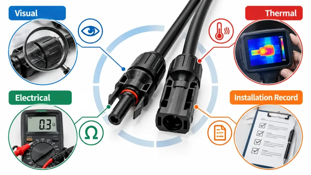
Once the circuit is in the required safe condition, investigation can include several layers.
Visual Inspection
Look for:
- discoloration
- softened or melted polymer
- cracking
- damaged locking tabs
- visible connector gaps
- loose gland nuts
- damaged cable jacket
- corrosion
- contamination
Installation Record Check
Identify:
- connector manufacturer/model
- mating counterpart
- cable size
- cable OD
- crimp tool/contact combination
- previous repairs
This is particularly useful for determining whether a mixed connector pair has entered the system during maintenance.
Thermal Inspection
Under appropriate operating and safety conditions, thermal imaging can help identify connections that are abnormally warm compared with similar circuits.
The comparison should consider load and environmental conditions.
Electrical / Laboratory Analysis
Where a recurring or serious failure needs root-cause analysis, more detailed methods can include:
- contact resistance measurement
- pull testing
- dimensional inspection
- X-ray examination
- destructive contact inspection
These are especially relevant when repeated failures appear across a batch or project.
What to Do After a Connector Has Melted
A visibly heat-damaged connector should not simply be pushed back together and returned to service.
Before replacing anything, document the failure where practical.
Record:
- connector markings
- both connector halves
- cable specification
- damage location
- polarity
- surrounding cable routing
- nearby connector condition
- photographs
Why keep this information?
Because once the failed parts are cut away and discarded, some of the best evidence of the root cause disappears.
Then investigate the cause before installing the replacement.
If the original problem was:
wrong crimp
and the replacement is made using the same incorrect tool, the failure can repeat.
If the original problem was:
cross-mating
and only the visibly damaged half is replaced, the incompatibility can remain.
If the original problem was:
incorrect cable OD
replacing the housing with the same connector configuration does not solve the sealing problem.
The repair should correct the cause, not only the melted component.
Preventing Failure in New Installations and Procurement
Connector reliability is easiest to improve before the system is energized.
For installation, control the full process:
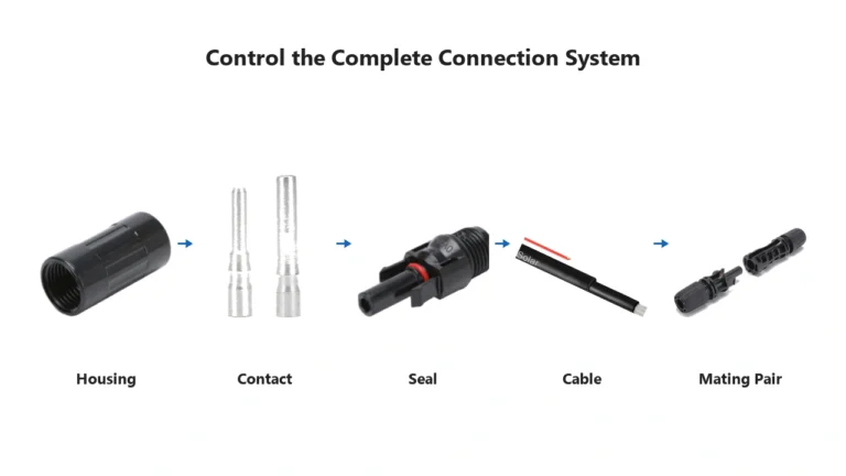
Correct cable → Correct contact → Correct tool → Correct housing → Correct mating pair → Correct sealing → Correct cable support
For procurement, ask for more than headline ratings.
A useful B2B connector specification should identify:
| Requirement | What to verify |
|---|---|
| Connector model | Exact product being supplied |
| Mating counterpart | Intended connector pair |
| Rated current | Exact cable/contact configuration |
| Rated voltage | Exact model |
| Conductor range | Contact compatibility |
| Cable OD | Seal compatibility |
| Contact material | Actual conductive system |
| Crimp tooling | Approved or specified die/tool |
| Assembly instructions | Repeatable installation process |
| Certification | Exact models and ratings covered |
| Traceability | Batch/product identification |
A buyer can therefore reduce connector failure risk before the first installation simply by preventing ambiguous combinations from entering the project.
For available UHCCY configurations, see Solar Connector.
Key Takeaway
MC4 connector failure is rarely caused by one dramatic event.
More often, the sequence looks like:
Installation / compatibility problem → increased resistance or degraded sealing → heat / corrosion / movement → further degradation → visible failure
The most useful rules are:
- A melted housing is usually evidence of an earlier problem, not the original problem itself.
- Poor crimps can create hidden high-resistance connections.
- Incomplete contact engagement matters even when the housings appear connected.
- Cross-mating can affect both contact performance and sealing.
- Cable OD matters because it affects the gland and environmental seal.
- Higher current amplifies the heating effect of an existing resistance defect.
- Mechanical cable stress can gradually degrade an otherwise correct installation.
- A connector can overheat without producing enough overcurrent to trip a breaker.
- Thermal imaging is most useful when comparing equivalent connections under similar conditions.
- After a failure, preserve evidence and identify the root cause before replacing the parts.
The best way to prevent PV connector failure is not simply to purchase a connector with a higher printed rating.
It is to control the complete connection system from cable selection through installation and long-term maintenance.