Table of Contents
An MC4 crimping tool should not be selected simply because its jaws are marked 2.5, 4 and 6 mm².
Those markings tell you which conductor cross-sections the die is intended to accommodate. They do not automatically prove that the die geometry matches the contact you intend to crimp.
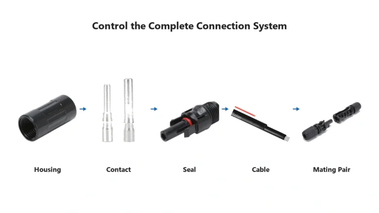
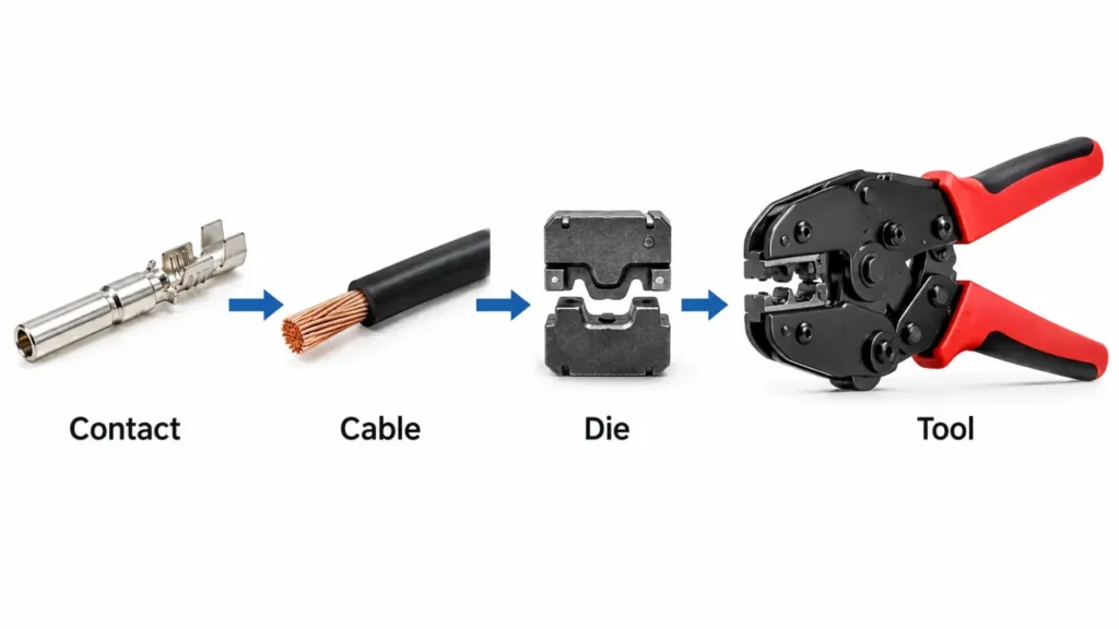
A reliable PV termination depends on a matched combination:
Connector contact → Conductor → Crimp die → Crimping tool
If one part of that combination is wrong, the finished crimp can look acceptable while still having poor mechanical retention or an unsuitable electrical interface.
UHCCY uses PV Connector Crimping Tool and Solar Connector Crimping Tool for its own products while using “MC4 crimping tool” in educational content because it remains a common search term.
For available crimpers, strippers, cutters and connector wrenches, see PV Connector Tools.
What Is an MC4 Crimping Tool?
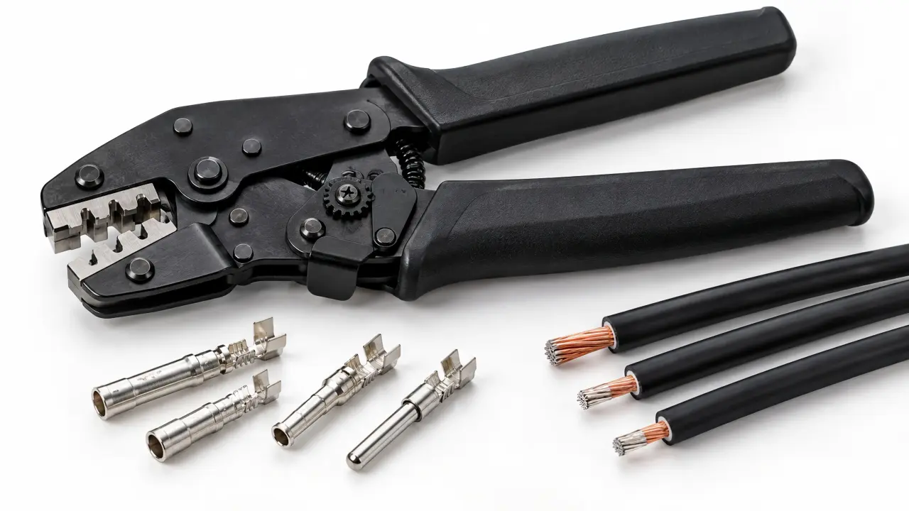
An MC4 crimping tool is a hand or powered tool used to compress a photovoltaic connector contact around a stripped conductor.
Its job is not simply to “squeeze the terminal.”
A correct crimp needs to create a controlled mechanical and electrical connection between:
the conductor strands
and:
the crimp barrel of the contact.
The crimping tool therefore controls one of the most important hidden interfaces inside a field-assembled PV connector.
Once the contact is inserted into the plastic housing, the quality of that crimp is no longer easily visible.
That is why tool selection matters before the connector is assembled.
Why 2.5 / 4 / 6 mm² Is Not Enough to Choose a Crimper
Many PV crimpers are marked:
2.5 mm²
4 mm²
6 mm²
These numbers describe conductor cross-sectional area.
They do not tell you everything about the contact.
Two contacts intended for the same 4 mm² conductor can still differ in:
- barrel width
- barrel thickness
- contact material
- contact plating
- open-barrel geometry
- crimp profile
- deformation limits
Therefore:
same cable size does not automatically mean same crimping die.
A tool should be matched to both:
conductor size
and:
contact design.
For conductor and cable terminology, see MC4 Connector Specifications.
The Four Parts That Must Match
A useful crimping-tool selection process starts with four components.
| Component | What to verify |
|---|---|
| Connector contact | Barrel design and intended crimp profile |
| Cable conductor | Cross-section and strand construction |
| Crimp die | Correct cavity and geometry |
| Crimping tool | Correct die mounting and complete crimp cycle |
Do not begin by asking:
“Which crimper handles 4 mm²?”
A better question is:
“Which tool and die are suitable for this exact 4 mm² conductor and contact?”
This distinction becomes increasingly important when installers work with more than one PV connector family.
Ratchet Crimper vs Ordinary Pliers
For manual PV connector termination, a ratchet mechanism is generally more suitable than ordinary pliers.
The main advantage is cycle control.
A ratcheting tool normally requires the jaws to move through the intended crimp cycle before the handles release.
This helps reduce partial crimps caused by stopping halfway.
However:
ratchet does not automatically mean correct crimp.
A ratcheting tool with the wrong die can produce a consistently wrong termination.
Ordinary combination pliers, slip-joint pliers and similar general-purpose tools do not provide a defined crimp profile and should not be treated as substitutes for a compatible connector crimper.
The full field procedure is covered separately in How to Crimp MC4 Connectors.
Why Die Profile Matters
The crimp die determines how the contact barrel is deformed around the conductor.
Different electrical terminals use different crimp geometries.
For example:
- ferrules
- cable lugs
- insulated terminals
- open-barrel contacts
- PV connector contacts
should not automatically use the same die.
Some online descriptions simplify PV dies as:
hex crimp
or:
solar crimp.
That can be useful as a general description, but the name of the profile is less important than whether the die matches the actual contact.
A die that physically closes around a terminal is not automatically the correct die.
The finished crimp geometry should follow the specification of the contact/tool system being used.
What Does “2546” Mean on a Solar Crimping Tool?
The designation 2546 is commonly seen on manual PV crimping tools.
It generally refers to the three common conductor cross-sections:
2.5 / 4 / 6 mm²
It is a useful product-model convention.
It is not an IEC crimping-tool classification and does not establish universal compatibility between different 2546 tools.
Two tools can both be marked 2546 while using different:
- die geometry
- jaw dimensions
- handle mechanisms
- adjustment systems
- contact compatibility
Treat 2546 as a cable-size indication—not proof that two crimpers are technically identical.
UHCCY’s PV Connector Crimping Tool UH-PT-CR01 uses dedicated positions for 2.5, 4 and 6 mm² PV conductors. The exact contact compatibility should still be confirmed before use.
mm² vs AWG on PV Crimping Tools
European and international PV products commonly identify conductor cross-section in mm².
North American products may use AWG.
A common working reference is:
| Metric | Common AWG reference |
|---|---|
| 2.5 mm² | 14 AWG |
| 4 mm² | 12 AWG |
| 6 mm² | 10 AWG |
These are useful selection references, but they should not be treated as exact mathematical equivalence for every cable construction.
What matters to the crimp is the actual conductor that the contact and tool were designed to terminate.
UHCCY therefore uses mm² as the primary specification and AWG as a secondary reference.
Dedicated Tool or Interchangeable Dies?
Both approaches can be useful.
Dedicated Crimping Tool
A dedicated tool keeps one die or crimping profile permanently associated with a defined application.
Advantages can include:
- fewer setup changes
- lower risk of installing the wrong die
- faster repetitive field work
- simpler tool identification
Interchangeable-Die Tool
An interchangeable tool frame can support several termination types by changing die sets.
This can reduce the number of tool bodies required.
It becomes more useful where technicians work with:
- several contact systems
- multiple terminal types
- different cable ranges
The tradeoff is process control.
If dies are frequently changed, the installer needs a reliable way to identify:
which die belongs to which contact.
For OEM or repeated production work, dedicated tooling can sometimes be easier to control even when an interchangeable system is more flexible.
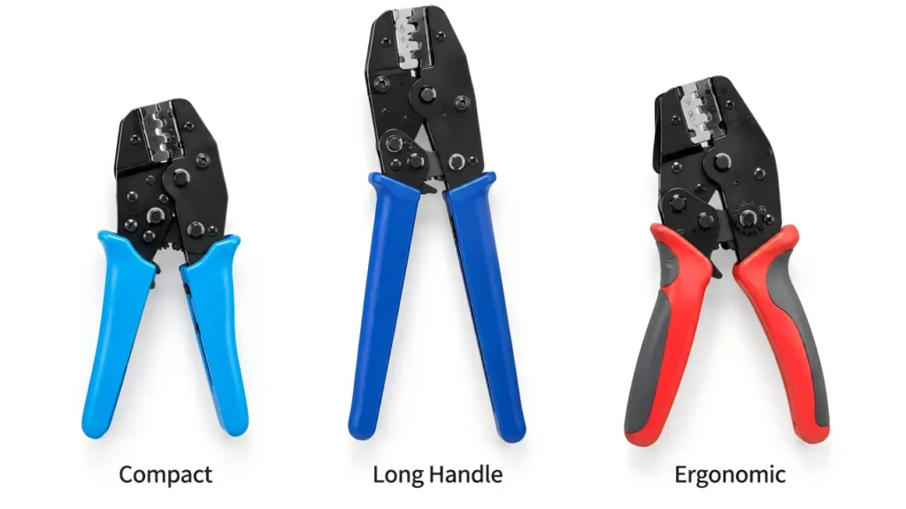
How Much Does Handle Design Matter?
Handle length and ergonomics do not change the electrical specification of the connector.
They change how the installer interacts with the tool.
A longer handle can provide greater mechanical leverage.
A compact tool can be easier to carry and position in restricted work areas.
An ergonomic handle can reduce fatigue during repeated use.
Therefore, when two crimpers support the same validated contact/conductor combination, the preferred format can depend on:
- installation frequency
- hand force
- workspace
- portability
- repetitive workload
UHCCY currently offers compact, long-handle and ergonomic configurations within its UH-PT-CR01 platform.
The important point is that:
handling preference comes after contact compatibility.
Do not choose a tool only because one handle looks more professional.
Tool Wear Matters More Than Most Buying Guides Mention
A crimping tool does not remain dimensionally perfect forever.
Repeated cycles can affect:
- die surfaces
- pivots
- ratchet mechanism
- adjustment
- jaw alignment
This matters because the crimp is produced by controlled deformation.
A tool that still opens and closes can therefore be mechanically functional while no longer producing the same termination geometry it produced when new.
The latest IEC 60352-2:2024 is particularly relevant here. It covers solderless crimped connections and includes guidance on crimp dimensions, tool condition and evaluation of crimped connections produced by different tool designs.
For professional use, this leads to a useful principle:
Tool condition is part of crimp quality.
A purchasing decision should therefore consider not only the initial tool price but also how the tool can be inspected and controlled over time.
Crimp Height and Why It Matters
For production-quality crimping, visual inspection alone is not always sufficient.
One useful process variable is crimp height or crimp depth, depending on the contact design.
Crimp height is the finished dimension of the compressed terminal at a defined measurement point.
It can help indicate whether:
- the die is closing correctly
- tool adjustment has changed
- the terminal is being over-compressed
- the terminal is being under-compressed
- tooling wear has changed the process
The correct dimension is contact-specific.
There is no universal crimp height that should be applied to every PV connector.
This is another reason generic articles giving one fixed “MC4 crimp depth” can be misleading.
For high-volume cable assembly, monitoring a specified crimp dimension can provide better process control than visually checking every contact and assuming they all look similar.
How to Check a Crimping Tool Before Use
A simple pre-use inspection can identify many obvious problems.
Check:
Die surface → Jaw alignment → Ratchet cycle → Adjustment → Cleanliness → Correct die identification
Look for:
- chipped or visibly worn die surfaces
- corrosion
- debris inside the crimp cavity
- loose pivots
- abnormal jaw movement
- incomplete ratchet release
- damaged adjustment mechanisms
- incorrect or unidentified dies
Do not modify a die with:
- files
- grinders
- drills
- hand polishing
to make a contact “fit better.”
If the contact does not match the die, identify the correct tooling instead.
Cheap vs Professional Crimping Tools
Price alone does not determine whether a crimping tool is suitable.
A lower-cost manual tool may be appropriate for occasional field work if:
- the die matches the contact
- the cable size is supported
- the ratchet works consistently
- finished crimps meet the required acceptance criteria
A more expensive tool becomes easier to justify when the application requires:
- high repetition
- documented process control
- replaceable or calibrated dies
- traceability
- long service life
- consistent production output
So the useful distinction is not:
cheap = bad
and:
expensive = good.
The better question is:
Can this tool repeatedly produce the required termination for the exact contact and cable combination?
That is the criterion that matters.
Crimper Only or Complete PV Tool Kit?
A crimping tool performs only one part of connector assembly.
A complete field process can require:
Cable Cutter → Wire Stripper → Crimper → Connector Wrench → Disconnect Tool
If an installer already owns suitable cutters, strippers and wrenches, purchasing only the crimper may be sufficient.
A complete kit is more useful for:
- new installation crews
- maintenance teams
- distributors
- contractors
- OEM service kits
- field technicians working across complete connector assemblies
The advantage of a tool kit is not simply convenience.
It also reduces the chance that one critical installation step is performed with an unsuitable general-purpose tool.
The full UHCCY range is organized under PV Connector Tools.
Field Installation and Production Use Need Different Tools
A technician making five terminations during maintenance and a cable-assembly factory making thousands of terminations have different priorities.
Field Use
Important factors include:
- portability
- manual operation
- fast setup
- multiple conductor sizes
- reliable ratchet mechanism
Repetitive Production
Additional concerns include:
- cycle consistency
- tooling identification
- wear monitoring
- crimp dimensions
- pull-test sampling
- traceability
- operator repeatability
For production work, the crimper becomes part of a controlled manufacturing process rather than simply a hand tool.
This distinction is often missing from general MC4 crimping-tool guides.
How to Choose an MC4 Crimping Tool
Use this order:
Identify connector contact → Confirm conductor size → Confirm required die profile → Select compatible tool → Check ratchet/full-cycle mechanism → Evaluate workload → Plan inspection and replacement.
1. Identify the Contact
Do not begin with the cable alone.
Identify the connector contact you need to crimp.
2. Confirm Conductor Cross-Section
Common PV conductors include 2.5, 4 and 6 mm², with other sizes used in specific connector systems.
3. Match the Die
Confirm that the die cavity is intended for both:
that conductor
and:
that contact geometry.
4. Check the Tool Mechanism
For manual repetitive crimping, a controlled full-cycle ratchet mechanism is generally preferable to uncontrolled hand pliers.
5. Consider Working Conditions
Choose handle size and tool format according to:
- field portability
- frequency of use
- available space
- operator workload
6. Plan How the Tool Will Be Checked
For repeated use, consider how you will identify:
- tool wear
- damaged dies
- changed adjustment
- deteriorating crimp quality
This final step is frequently overlooked.
A Better Purchasing Specification for Crimping Tools
For B2B procurement, avoid an RFQ such as:
“Need MC4 crimper 2.5–6 mm².”
A better specification includes:
| Requirement | What to define |
|---|---|
| Application | PV connector contact crimping |
| Connector/contact | Intended contact model or geometry |
| Conductor range | Required mm² |
| Tool mechanism | Manual ratchet / other |
| Die | Fixed or interchangeable |
| Crimp profile | Required for contact |
| Workload | Occasional field / repeated installation / production |
| Handle format | Compact / long handle / ergonomic |
| Packaging | Individual / kit |
| OEM | Color, logo, packaging if required |
| QC requirement | Tool inspection / crimp verification expectations |
That makes it much easier to compare tools that otherwise all appear to be the same “2546 crimper.”
For the UHCCY manual 2.5 / 4 / 6 mm² platform, see UH-PT-CR01 PV Connector Crimping Tool.
Common MC4 Crimping Tool Selection Mistakes
The most common mistakes are:
Choosing by cable size alone
The contact geometry still has to match.
Assuming every 2546 tool is identical
2546 primarily describes the nominal conductor-size range.
Assuming ratchet automatically means correct
The wrong die can complete a perfect ratchet cycle and still make the wrong crimp.
Using a ferrule or cable-lug crimper for a PV contact
The terminal may fit physically while requiring another profile.
Ignoring tool wear
A frequently used tool can drift from its original process condition.
Buying the most expensive tool without checking the connector
Price does not establish contact compatibility.
Using one tool for every connector family
Different connector contacts can require different tooling even at the same cable size.
Key Takeaway
Selecting an MC4 crimping tool is not primarily about choosing between cheap and expensive tools.
It is about matching the contact, conductor, die and tool.
Remember:
- 2.5 / 4 / 6 mm² markings describe conductor size—not universal connector compatibility.
- The crimp die must match the contact geometry as well as the conductor.
- A ratchet improves cycle consistency but does not correct an unsuitable die.
- 2546 is a useful size convention, not a universal crimping standard.
- Handle style affects usability more than electrical performance.
- Tool wear and adjustment can affect crimp consistency over time.
- Production crimping requires more process control than occasional field work.
- A complete PV tool kit can cover cutting, stripping, crimping, assembly and maintenance.
- For purchasing, specify the termination system—not just the crimper size.
The simplest useful rule is:
Contact → Cable → Die → Tool.
Choose in that order, not the other way around.