Table of Contents
If you need to know how to disconnect MC4 connectors, the most important rule comes before touching the locking tabs:
do not separate a PV connector while it is carrying load current.
A photovoltaic connector is normally designed to remain securely locked during operation. The disconnect tool releases that locking mechanism so the two connector housings can be separated without prying, twisting or damaging the latch.
The basic process is:
De-energize the circuit → identify the connector → engage the correct disconnect tool → release the locking tabs → separate the housings → inspect and protect the open connectors.
For PV installation tools, see PV Connector Tools.
Why MC4 Connectors Need a Disconnect Tool
PV connectors are designed to resist accidental separation.
When the two mating halves are pushed together, locking tabs engage with the corresponding housing.
This is useful outdoors because cable movement, vibration and handling should not be able to separate an energized PV connection simply by pulling on it.
The same locking mechanism means that intentionally disconnecting the pair requires the latch to be released first.
This leads to an important distinction:
a disconnect tool is not intended to pull the connector apart.
Its job is to release the lock.
Once the locking tabs are released, the connector housings can be separated using their intended gripping areas.
Before You Disconnect the Connector
The connector should first be placed in the electrical condition required by the equipment and connector manufacturer’s procedure.
This matters because breaking a loaded DC circuit can produce an electrical arc.
Do not assume that turning off one piece of equipment automatically makes every PV conductor safe. Solar modules can continue producing DC voltage whenever sufficient light is available.
The required isolation sequence depends on the actual system architecture, equipment and applicable electrical procedures.
For general array polarity and wiring concepts, see the MC4 Connector Wiring Guide.
How to Disconnect MC4 Connectors
Once the system has been placed in the appropriate safe condition, the mechanical disconnection itself is simple.
Step 1: Identify the Locking Points
Locate the locking tabs or latch areas on the mated connector.
Do not start by pulling on the cable.
The cable gland and conductor termination are not intended to be used as handles for forcing the connection apart.
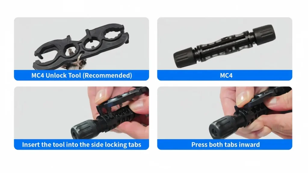
Step 2: Position the Disconnect Tool
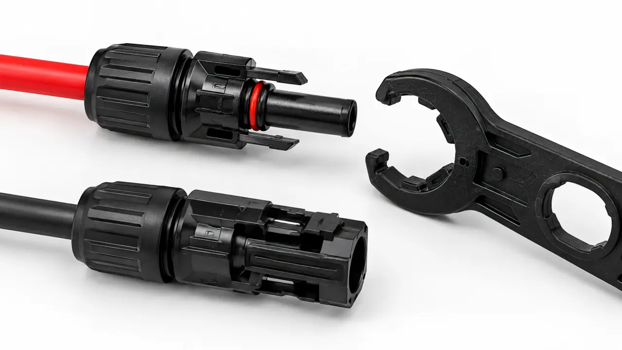
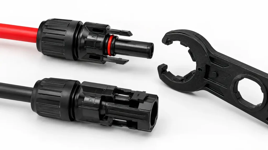
Place the correct disconnect tool over the connector so its release features engage the locking tabs.
The exact tool shape depends on the connector family.
Do not assume that every wrench marketed as an “MC4 tool” correctly releases every PV connector on the market.
Step 3: Release the Lock
Apply enough pressure with the tool to disengage the locking tabs.
The objective is to release the mechanical latch—not to deform the housing.
If excessive force is necessary, stop and check:
tool position → connector model → locking mechanism → contamination or damage.
Step 4: Separate the Connector Housings
With the lock released, grip the connector bodies and pull them apart along the mating axis.
Do not pull from the cable.
Avoid excessive twisting, bending or side loading.
Step 5: Inspect Both Connector Halves
After separation, check the housing, locking features, sealing areas and visible contact region before the connector is reused.
The sequence is therefore compact:
Identify → Release → Separate → Inspect.
Can You Disconnect MC4 Connectors Without a Tool?
You will find many online guides showing connectors being opened by:
- squeezing the locking tabs with fingers
- using a screwdriver
- using pliers
- improvising another object
The fact that a connector can sometimes be opened this way does not make it the preferred method.
A screwdriver can concentrate force on a small section of the housing or locking feature.
Pliers can crush or permanently deform polymer components.
Repeatedly forcing the tabs by hand can also damage a locking feature that was designed to be opened using the intended release geometry.
More importantly, some locking PV connectors are specifically designed to require a tool for opening.
For U.S. installations, that tool requirement is also part of the safety concept behind accessible PV mating connectors rather than simply an inconvenience.
For routine installation and maintenance, the practical rule is:
Use the correct disconnect tool for the connector being serviced.
One Tool or Two?
This depends on what you are doing.
To release the locking connection, one correctly designed unlocking tool may be sufficient for some connector systems.
To assemble or loosen cable-gland components, two wrench-type tools may be used so one part can be held while the other is tightened or loosened.
These are different operations.
Do not confuse:
unlocking the mating interface
with:
disassembling the connector body.
A connector that has already been field assembled should not be dismantled simply because the cable connection needs to be unplugged.
For connector assembly and termination, see How to Crimp MC4 Connectors.
What to Check After Disconnecting
Separating the connector creates an opportunity to inspect a connection that may have been outdoors for years.
Look for:
| Area | Check for |
|---|---|
| Housing | Cracks, distortion or melted areas |
| Locking tabs | Broken, bent or weakened latch features |
| Sealing interface | Damage, contamination or displaced sealing parts |
| Contact area | Corrosion, discoloration or visible contamination |
| Cable entry | Mechanical strain or damaged jacket |
| Identification | Manufacturer and model markings |
If a connector is obviously damaged, replacing the affected component with the correct documented system is preferable to trying to reshape or repair the housing.
Protect Open Connectors From Contamination
A disconnected connector is no longer in its normal mated state.
Do not leave open PV connector interfaces exposed unnecessarily to:
dust, moisture, dirt, insects or construction debris.
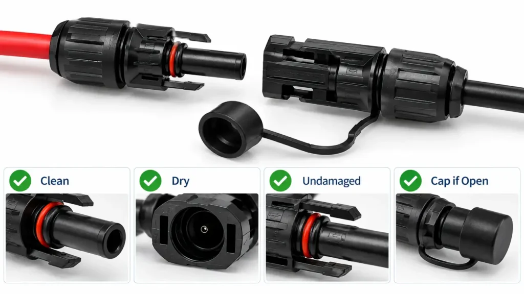
For its Original MC4 system, Stäubli specifies that unmated connectors should be protected from environmental contamination using appropriate sealing caps.
This is particularly important during:
- module replacement
- inverter maintenance
- construction delays
- temporary system isolation
- cable rerouting
A connector contaminated while open should not simply be pushed back together to hide the contamination.
Common Disconnecting Mistakes
The most common problems are simple mechanical shortcuts.
Pulling on the Cable
This transfers force through the cable gland and internal termination rather than the intended connector gripping surfaces.
Twisting the Connectors Apart
A locking axial connector should normally be released and separated in the intended direction rather than unscrewed or aggressively twisted unless the manufacturer specifically defines such a mechanism.
Prying With a Screwdriver
This can damage the locking feature or housing even if the connector appears usable afterward.
Disconnecting Under Load
This can create an electrical arc and is specifically prohibited for connector systems not designed as load-break devices.
Reusing a Damaged Lock
A connector that no longer retains correctly should not be treated as repaired simply because it can still carry current.
Leaving Open Ends Exposed
Dust or moisture introduced during maintenance can become trapped inside the connection when it is remated.
Reconnecting After Maintenance
Before reconnecting, confirm that both halves remain:
clean → dry → undamaged → documented mating counterparts.
Then mate them according to the connector manufacturer’s instructions and verify full engagement.
Do not use maintenance as an opportunity to substitute whichever similar connector is available.
This is especially relevant in older PV arrays where a damaged connector may be replaced years after the original module installation.
A replacement that looks identical may belong to another connector system.
The 2026 NEC has further tightened U.S. requirements around non-identical PV connector intermatability by requiring the relationship to be documented by both manufacturers.
For the full issue, see MC4 Connector Compatibility.
Choosing an MC4 Disconnect Tool
The commercial term MC4 disconnect tool covers a wide range of plastic and metal wrenches.
For purchasing, do not select the tool only by shape or price.
Check:
| Requirement | Why it matters |
|---|---|
| Connector family | Release geometry must match the latch |
| Unlocking function | Tool must reach and release the locking tabs |
| Assembly function | Some tools also tighten/hold gland components |
| Material | Must withstand repeated field use |
| Tool access | Connector spacing may restrict insertion |
| Product documentation | Confirms intended use |
For installers handling more than one PV connector family, labeling the tools by connector system can reduce accidental misuse.
UHCCY offers connector wrenches and related installation equipment under PV Connector Tools.
Key Takeaway
Disconnecting an MC4 or similar PV connector should not be treated as a force problem.
The correct logic is:
electrical isolation → correct tool → release the lock → separate the housings → inspect → protect or reconnect correctly.
The most important points are:
Never use the cable as a pulling handle.
Do not pry the locking mechanism with improvised tools when the correct release tool is available.
Do not disconnect a PV connector under load unless the exact system is specifically designed and approved for current interruption.
Inspect damaged locking and sealing features before reuse.
Protect unmated connector interfaces from contamination.
When replacing a connector during maintenance, verify the mating system rather than matching by appearance.
The disconnect tool is therefore not just a convenience accessory. It is part of maintaining the locking connector as the connection system was designed to be serviced.