
Choose the pole configuration according to the AC distribution system, then select the rated current according to the connected load and protective-device coordination. Current ratings from 6A to 63A are available for both product configurations.
Automatic Transfer Switch
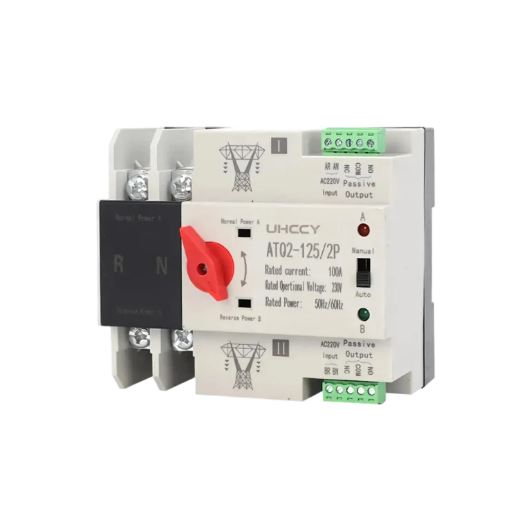
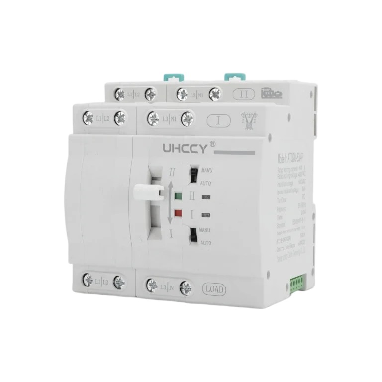
Dual Power Automatic Transfer Switch 6–63A 2P/4P – UH-PW-ATQ2
Model UH-PW-ATQ2
Compact PC-class dual power automatic transfer switch for automatic changeover between two AC sources, available in 2P/4P and 6–63A with Source I priority and Auto/Manual operation.
- Automatic Changeover
- Source I Priority
- Auto Return
Rated Voltage
AC 110 / 220 / 400 V
Rated Current
63 A
Pole Configuration
2P / 4P
Confirm the rated voltage, rated current, number of poles, conductor size, backup power source, load characteristics, and upstream protection before installation.
Overview
Product Overview
The UH-PW-ATQ2 is a compact PC-class automatic transfer switch designed to change a connected load between two AC power sources. In automatic mode, Source I operates as the priority source. When Source I becomes unavailable or moves outside the monitored voltage range, the ATS initiates transfer to Source II and can automatically return when Source I recovers.
The design is particularly suitable for solar and grid applications where the AC output of a PV inverter is connected as the preferred source and utility power is used as the alternate source. It can also be applied to other compatible normal and standby AC power arrangements. The switch operates on the AC side of the system and is not intended for direct PV string DC switching.
Available in 2P and 4P configurations with rated current options from 6A to 63A, the UH-PW-ATQ2 combines voltage monitoring, source and load status indication, manual override and DIN-rail installation in a compact format for distribution boards and backup-power systems.
Features
Key Product Features
Automatic Changeover
Source I Priority
Auto Return
Auto / Manual
Voltage Monitoring
DIN Rail Mounting
Automatic Changeover
Monitors the two connected AC sources and automatically initiates transfer when the priority source becomes unavailable or abnormal.
Source I Priority & Auto Return
Source I has priority in automatic mode, with automatic return to the preferred source after acceptable supply conditions are restored.
Fast Switching Mechanism
The switching mechanism completes the changeover operation in less than 50 ms once transfer is initiated.
Automatic & Manual Operation
Selectable Auto and Manual modes support normal automatic operation as well as controlled switching during commissioning or maintenance.
Voltage Monitoring & Indication
Integrated voltage monitoring and front indicators provide clear visual status for Source I, Source II and the connected load.
Compact DIN-Rail Design
Modular construction and standard 35 mm DIN-rail mounting simplify integration into residential and commercial distribution boards.
Technical Data
Technical Specifications
Electrical ratings, transfer characteristics and operating conditions for the UH-PW-ATQ2 series.
Electrical Characteristics
| Parameter | Specification |
|---|---|
| Rated Voltage | AC 110 / 220 / 400 V |
| Rated Current | 63 A |
| Rated Frequency | 50/60 Hz |
| Pole Configuration | 2P / 4P |
| Rated Insulation Voltage Ui | 690 V |
| Rated Impulse Withstand Voltage Uimp | 8 kV |
| Transfer Class | PC Class |
| Utilization Category | AC-31B |
| Rated Conditional Short-Circuit Current Iq | 5 kA |
| Short-Circuit Protective Device | RT16-00-63A Fuse |
| Power Sources | Normal + Backup |
Control & Switching
| Parameter | Specification |
|---|---|
| Operating Mode | Automatic / Manual |
| Automatic Return | Yes |
| Rated Control Voltage Us | AC 110 / 220 V, 50/60 Hz |
| Control Voltage Range | 85%–110% Us |
| Changeover Operation Time | <50 ms |
| Voltage Monitoring | Overvoltage / Undervoltage |
| Source Status Indication | Source I / Source II |
| Load Status Indication | Load ON |
Mechanical & Environmental
| Parameter | Specification |
|---|---|
| Mounting | 35 mm DIN Rail |
| Protection Degree | IP30 |
| Operating Temperature | -5°C to +40°C |
| Storage Temperature | -25°C to +55°C |
| Installation Altitude | ≤2,000 m |
| Pollution Degree | 3 |
| Recommended Screw Torque | 2.5 N·m |
Selection
2P & 4P Model Selection
| Model | Poles | Rated Current | Typical Configuration |
|---|---|---|---|
| UH-PW-ATQ2-2P | 2P | 6–63 A | Single-phase L + N |
| UH-PW-ATQ2-4P | 4P | 6–63 A | Three-phase 3P + N |
Packaging
Packaging Information
Standard packing data for wholesale ordering and shipment planning.
| Configuration | Inner Box | Net Weight | Qty / Carton | Master Carton | Gross Weight |
|---|---|---|---|---|---|
| 2P | 120 × 55 × 85 mm | 395 g | 48 pcs | 460 × 255 × 270 mm | 19.5 kg |
| 4P | 120 × 90 × 85 mm | 590 g | 30 pcs | 460 × 255 × 270 mm | 18.2 kg |
Applications
Where This Product Is Used

Commercial Buildings
Protection, switching, distribution and enclosure components for commercial and light-industrial electrical installations.
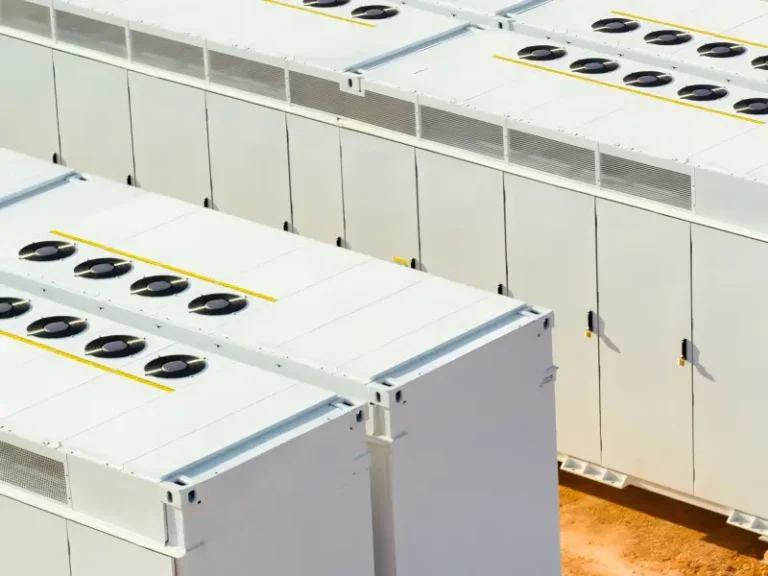
Energy Storage Systems
DC protection, isolation and switching components for battery energy storage and related DC power systems.
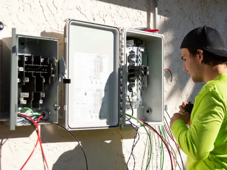
Residential Electrical
Protection, switching and backup-power components for residential distribution boards and low-voltage electrical systems.
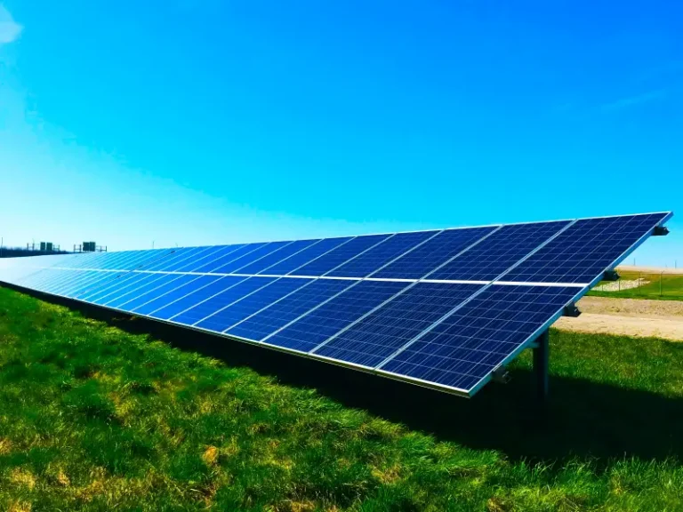
Solar PV Systems
Protection, connectivity and distribution components for photovoltaic arrays, string circuits and related solar DC systems.
Installation
Installation Guidance
Mount the UH-PW-ATQ2 on a standard 35 mm DIN rail inside a suitable low-voltage distribution enclosure.
Connect the preferred AC supply to Source I and the alternate supply to Source II according to the terminal markings. For solar applications, the inverter AC output can be connected as the priority source and utility power as the alternate source.
For 4P installations, verify the correct phase sequence before energizing the switch. Tighten terminal connections to approximately 2.5 N·m and confirm that all conductors are securely connected.
Select Manual mode before manual changeover operation. Suitable upstream overload and short-circuit protection should be provided according to the electrical system design.
Important Notes
Confirm the rated voltage, rated current, number of poles, conductor size, backup power source, load characteristics, and upstream protection before installation.
FAQ
Frequently Asked Questions
What is the UH-PW-ATQ2 used for?
The UH-PW-ATQ2 automatically transfers a connected AC load between two available power sources. Source I operates as the preferred source in automatic mode, while Source II provides the alternate supply.
What current ratings are available?
The series is available in 6A, 10A, 16A, 20A, 25A, 32A, 40A, 50A and 63A rated-current options.
What is the difference between the 2P and 4P versions?
The 2P version is intended for applicable single-phase line-and-neutral systems. The 4P version switches three phases and neutral for corresponding three-phase distribution systems.
Can this ATS be used with a solar inverter and the power grid?
Yes. The UH-PW-ATQ2 can be used on the AC side of a solar system, with a compatible inverter AC output and utility grid connected as the two sources. It is not intended for direct PV string DC switching.
Is the transfer completely uninterrupted like a UPS?
No. An automatic transfer switch is not a UPS. The switching mechanism operates in less than 50 ms once transfer is initiated, but source-monitoring and transfer-delay logic may also apply. Connected equipment should therefore be suitable for transfer-type power interruption.
Does the ATS provide overload or short-circuit protection?
The UH-PW-ATQ2 is a PC-class transfer switching device and does not replace dedicated overload or short-circuit protection. Suitable upstream protective devices should be selected according to the electrical system.
Explore More
Related Products
Other recently published products from the same category.
Need More Information About This Product?
Contact UHCCY for technical details, product selection, samples, pricing, and OEM/ODM requirements.