Product Category

Automatic Transfer Switch

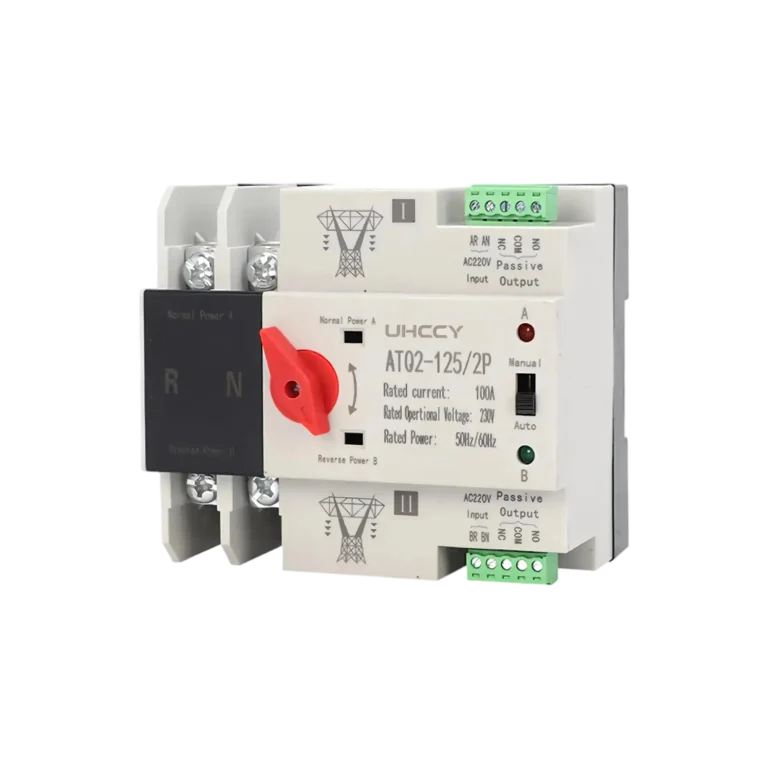
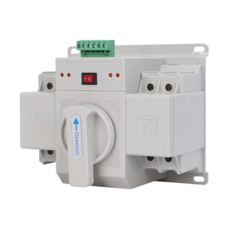
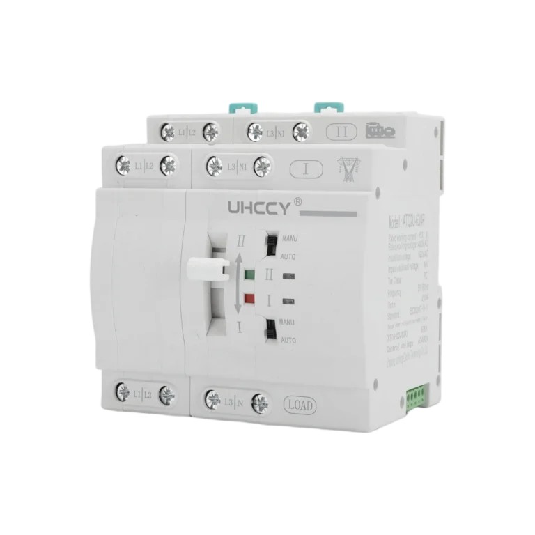
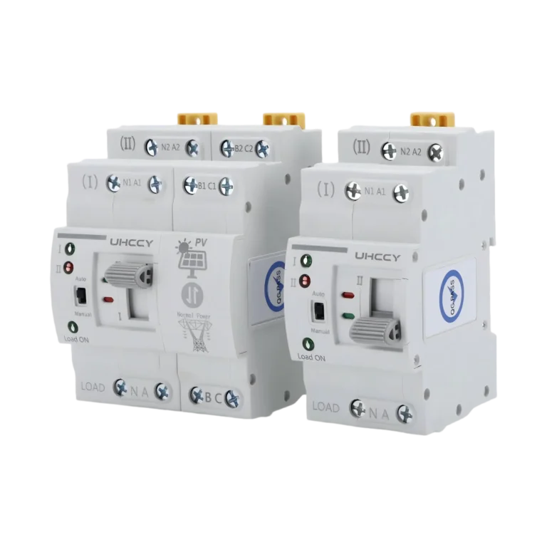
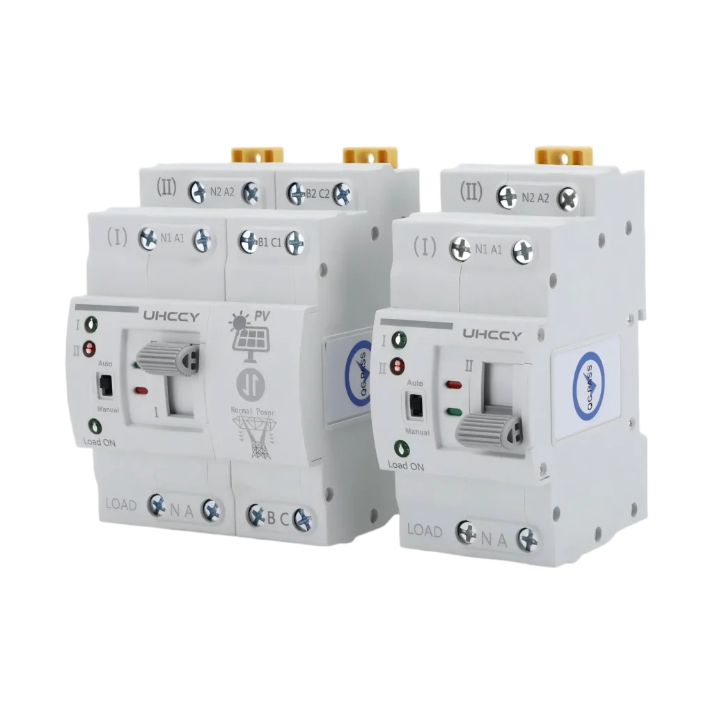
UHCCY Automatic Transfer Switches (ATS) provide controlled transfer between normal and alternative power sources for low-voltage distribution systems. Choose from compact solutions for residential and distributed power applications to configurations designed for commercial, industrial, generator, solar and energy storage systems.

Dual Power Automatic Transfer Switch 2P/4P, Up to 63A – UH-PW-ATQ2

Product Range

UHCCY Automatic Transfer Switch Products

Browse available models here, then use the comparison table below to compare family-level specifications.

Overview

About Automatic Transfer Switch

UHCCY Automatic Transfer Switches are designed to transfer electrical loads between two available power sources when the preferred supply fails or moves outside the permitted operating conditions. Depending on the selected model and system design, an ATS can be used between utility and generator, two utility supplies, or approved inverter and backup power sources.

Our ATS range is intended for residential distribution, commercial buildings, industrial equipment, solar and energy storage systems, generator backup installations and low-voltage panel assemblies. Model selection should consider rated current, number of poles, source configuration, transfer logic, switching time, installation method and coordination with circuit protection devices.

What Is an Automatic Transfer Switch?

An Automatic Transfer Switch, commonly abbreviated as ATS, is a switching device used to transfer an electrical load between a preferred power source and an alternative power source.

In a typical backup power system, the preferred source may be the utility grid while the alternative source is a generator. Other system architectures may use two independent utility supplies, a grid supply with an inverter, or another engineered backup source.

The ATS monitors relevant source conditions through its controller. When the preferred source becomes unavailable or moves outside the configured operating conditions, the controller initiates the transfer sequence. Once the preferred source is restored and remains stable for the required period, the system may transfer the load back according to the selected operating logic.

The exact monitoring functions, transfer delay, return logic and control interfaces vary between ATS series and must therefore be verified on the individual product page.

How an Automatic Transfer Switch Works

A typical automatic transfer sequence can be divided into four stages:

1. Normal Source Monitoring

During normal operation, the load remains connected to the preferred source while the ATS controller monitors the conditions supported by the selected model.

2. Abnormal Source Detection

If the preferred source fails or an applicable monitored parameter moves outside its permitted range, the controller recognizes the abnormal condition.

3. Transfer to the Alternative Source

After confirming that the alternative source is available and suitable for connection, the ATS operates its switching mechanism and transfers the load according to the defined sequence.

For generator applications, compatible ATS controllers may also provide a generator start signal before transferring the load.

4. Return to the Preferred Source

When the normal source returns and remains stable, an automatic-return system can transfer the load back after the configured delay. Generator installations may subsequently issue a stop signal after the required cool-down sequence.

The exact sequence must always be confirmed from the selected model because transfer time, delay settings, source monitoring and generator interfaces are not identical across all ATS products.

Common Types of Automatic Transfer Switch

ATS products can be classified in several ways depending on switching architecture, installation method and application.

Compact / DIN-Rail Automatic Transfer Switch

Compact ATS devices are commonly integrated into distribution boards where installation space is limited. They are particularly useful for residential backup systems, small commercial installations, telecommunications equipment, solar systems and distributed electrical panels.

PC-Class Automatic Transfer Switch

A PC-class ATS is primarily designed to perform source switching and transfer. Circuit overload and short-circuit protection are normally coordinated with separate protective devices within the electrical system.

PC-class designs can be advantageous where dedicated switching performance, electrical endurance or relatively fast transfer is required.

CB-Class Automatic Transfer Switch

CB-class transfer equipment incorporates circuit-breaker-based switching architecture and can combine transfer functionality with specified protective characteristics.

Whether PC-class or CB-class equipment is appropriate depends on system protection philosophy, switching duty, short-circuit coordination, maintenance requirements and project specifications.

Always confirm the ATS classification of the exact UHCCY model before specification.

ATS Is Part of the Complete Power Distribution System

An automatic transfer switch should not be selected as an isolated component.

The ATS must operate correctly with:

  • the normal power source;
  • the alternative power source;
  • upstream circuit protection;
  • downstream load characteristics;
  • neutral and grounding arrangements;
  • generator controls where applicable;
  • enclosure and panel design;
  • conductor sizing;
  • system short-circuit requirements;
  • and the required transfer sequence.

For this reason, UHCCY recommends selecting an ATS from complete source and load information rather than choosing only by rated current.

Key Advantages

Why Choose UHCCY Automatic Transfer Switch

Automatic Source Transfer

Continuously monitors the selected power source conditions and initiates transfer to an alternative source according to the control logic of the chosen ATS model.

Dual-Power System Integration

Suitable for common dual-source architectures such as utility-to-utility, utility-to-generator and approved grid-to-inverter or backup power configurations.

Flexible Pole Configurations

Available configurations support different single-phase and multi-wire distribution requirements. Select the pole arrangement according to the system, neutral strategy and local installation requirements.

Automatic & Manual Operation

Selected ATS models combine automatic transfer control with manual operation for commissioning, maintenance and emergency system management.

Compact Panel Integration

Compact designs and DIN-rail or panel-mounting options simplify integration into distribution boards, control cabinets and OEM electrical assemblies.

OEM & Project Support

UHCCY supports distributors, panel builders and electrical equipment manufacturers with model selection, technical documentation, private-label requirements, packaging and repeat-order supply.

Model Selection

Automatic Transfer Switch Model Comparison

Compare the main family-level parameters, then open a model for its complete specifications and inquiry details.

ModelRated VoltageRated CurrentPower SourcesOperating ModePole Configuration
UH-PW-AT0163A CB-Type Automatic Transfer Switch, 2P / 3P / 4P – UH-PW-AT01 220V / 380V AC63ANormal + BackupAutomatic / Manual2P / 3P / 4P
UH-PW-AT02100A / 125A PC-Class Automatic Transfer Switch – UH-PW-AT02 AC 110 / 230 / 380 V100A / 125AUtility / Backup / GeneratorAutomatic / Manual2P / 3P / 4P
UH-PW-ATQ2Dual Power Automatic Transfer Switch 6–63A 2P/4P – UH-PW-ATQ2 AC 110 / 220 / 400 V63 ANormal + BackupAutomatic / Manual2P / 4P
UH-PW-ATQ2-1DIN Rail Automatic Transfer Switch UH-PW-ATQ2-1 AC 230 / 400 V63 ANormal + BackupAutomatic / Manual2P / 4P

Selection Guide

How to Select the Right Model

How to Select the Right Automatic Transfer Switch

Selecting an ATS requires more than matching the current rating. Use the following information to narrow the product family before comparing individual models.

1. Define the Two Power Sources

Start by identifying both sources clearly.

Examples include:

  • utility + generator;
  • utility + utility;
  • utility + inverter;
  • utility + energy storage inverter;
  • two independent AC supplies.

Confirm the nominal voltage, frequency, phase configuration and grounding arrangement of both sources.

2. Determine the Required Load Current

The ATS rated current must be appropriate for the connected load and switching duty.

Do not select only from the normal running current. Consider the actual load characteristics, including motor starting current, inductive loads, transformers, compressors or other equipment with significant inrush current.

Upstream and downstream protective-device coordination must also be considered.

3. Select the Correct Number of Poles

The pole configuration depends on the electrical system and whether the neutral conductor must be switched.

For typical compact UHCCY ATS products, 2P and 4P configurations cover common single-phase and multi-wire applications.

Neutral switching requirements should be determined from the grounding system, source arrangement and applicable electrical regulations rather than simply choosing the highest number of poles.

4. Determine PC-Class or CB-Class Requirements

Use the project protection philosophy to determine whether the system requires:

  • a dedicated transfer-switch architecture; or
  • a circuit-breaker-based transfer architecture.

Do not assume that every ATS provides overload or short-circuit protection. Protective functions must be verified on the exact product.

5. Define the Required Transfer Sequence

Confirm:

  • preferred source;
  • transfer delay;
  • alternative source availability;
  • automatic or manual operation;
  • automatic return requirements;
  • return delay;
  • generator start/stop requirements;
  • and any external control signals.

These functions can differ significantly between ATS controllers.

6. Check Transfer Time Requirements

An ATS normally introduces an interruption while changing power sources.

Applications with sensitive electronic equipment may require additional power-continuity equipment such as a UPS. ATS switching time alone should not be treated as equivalent to a no-break power supply.

Always compare the permitted interruption time of the load with the switching characteristics of the exact ATS model.

7. Confirm Installation Method

Check:

  • DIN-rail or panel mounting;
  • available enclosure space;
  • wiring direction;
  • conductor size;
  • terminal accessibility;
  • operating clearance;
  • ventilation requirements;
  • and maintenance access.

Compact installation dimensions can be especially important in residential distribution boards and OEM control panels.

8. Confirm Documentation and Market Requirements

Before placing a project order, identify the destination market and required technical documentation.

Certification, test reports and applicable standards may vary by series, current rating and target market. Approval should therefore be confirmed at model level rather than assumed for the complete ATS category.

Use Cases

Automatic Transfer Switch Applications

Residential Backup Power

Automatic transfer switches can manage changeover between the normal household supply and an approved alternative source such as a backup generator or inverter system. Compact DIN-rail designs are particularly suitable for integration into residential distribution boards.

Generator Backup Systems

A compatible ATS can monitor utility supply conditions, initiate the generator start sequence and transfer selected loads after the generator source becomes stable. Generator control functionality must be confirmed for the exact ATS controller.

Solar & Energy Storage Systems

Automatic transfer equipment can form part of solar, hybrid inverter and battery energy storage architectures where loads must be transferred between grid and approved alternative AC sources. Source characteristics and inverter compatibility must be checked during system design.

Panel Building & OEM Equipment

Panel builders and electrical equipment manufacturers can integrate ATS devices into distribution boards, backup-power panels and customized electrical assemblies. UHCCY can support model matching and OEM requirements for repeat production.

Installation

Installation & Compatibility

Automatic transfer switches should be installed as part of a correctly engineered low-voltage distribution system.

Before installation, confirm that the rated voltage, current, pole configuration and control supply of the ATS match both power sources and the connected load.

Both incoming sources must be connected to their designated ATS terminals and the load must be connected to the specified output. Never interchange normal-source, alternative-source and load terminals unless the product wiring diagram specifically permits the configuration.

The installation must also consider:

  • upstream short-circuit and overload protection;
  • conductor size and terminal capacity;
  • phase sequence where applicable;
  • neutral switching requirements;
  • grounding arrangement;
  • generator start/stop contacts;
  • source monitoring connections;
  • enclosure temperature and ventilation;
  • required electrical clearances;
  • and safe access for testing and maintenance.

For generator systems, verify that the ATS controller provides the required generator control interface and that transfer occurs only after the generator output has reached acceptable operating conditions.

For inverter, solar and energy storage applications, confirm that the alternative AC source is compatible with the ATS monitoring and switching characteristics.

An ATS is not automatically a no-break power device. Where the connected equipment cannot tolerate the interruption associated with source transfer, coordinate the ATS with an appropriate UPS or other continuity solution.

Installation, commissioning and maintenance should be performed by qualified electrical personnel in accordance with the product documentation and applicable local electrical regulations.

Compliance

Certifications & Standards


Certifications & Standards

Automatic Transfer Switching Equipment is covered internationally by the IEC 60947-6-1 family of requirements for transfer switching equipment.

Applicable requirements can include characteristics related to switching performance, operating sequences, utilization categories, electrical endurance, short-circuit behavior, markings and verification testing.

The applicable standard edition, product classification and certification scope must be confirmed for each UHCCY ATS model and target market.

Do not assume that every product in the Automatic Transfer Switch category carries identical certificates or approvals. For project specification, request the documentation corresponding to the exact model, rated current, pole configuration and destination market.

Where required, UHCCY can provide available model-specific technical documentation for review before sample or bulk-order approval.

FAQ

Frequently Asked Questions

Common technical and purchasing questions about this product category.

What is an Automatic Transfer Switch?

An Automatic Transfer Switch (ATS) transfers an electrical load between a normal power source and an alternative source according to the monitoring and control logic of the selected device. It is commonly used in backup and dual-power distribution systems.

How does an Automatic Transfer Switch work?

The ATS monitors the preferred power source. When an applicable abnormal condition is detected, the controller verifies the alternative source and initiates the transfer sequence. When the preferred source returns and stabilizes, compatible models can automatically transfer the load back.

What is the difference between an ATS and a manual transfer switch?

An ATS can initiate source transfer automatically according to its monitoring and controller settings. A manual transfer switch requires an operator to perform the changeover. Some ATS products also include a manual operating mode for commissioning or maintenance.

Can an Automatic Transfer Switch work with a generator?

Yes, compatible ATS models can be used in utility-to-generator systems. Generator applications may require start/stop contacts, transfer delays and source-stability logic, so generator functionality must be confirmed on the selected model.

Can an ATS be used with solar or energy storage systems?

Yes, an ATS can form part of certain solar, hybrid inverter and battery energy storage systems. The AC source characteristics, inverter operating mode, neutral arrangement and transfer logic must be compatible with the selected ATS.

What is the difference between PC-Class and CB-Class ATS?

PC-class ATS products are primarily transfer-switching devices and are generally coordinated with separate circuit protection. CB-class designs use circuit-breaker-based switching architecture and can provide specified protective functions. Always check the classification and protection characteristics of the exact model.

Should I choose a 2P or 4P ATS?

The correct pole configuration depends on the phase system and whether the neutral conductor must be switched. A 2P configuration is commonly associated with single-phase applications, while 4P configurations are used where all required conductors, including neutral where applicable, must be transferred. Final selection should follow the system grounding and neutral design.

Is an Automatic Transfer Switch also a circuit breaker?

Not necessarily. The primary function of an ATS is source transfer. Some CB-class products incorporate specified circuit-breaker protection, while many PC-class ATS products require separate upstream or downstream protective devices.

Does an ATS provide uninterrupted power?

Not necessarily. Most electromechanical ATS systems introduce a short interruption while transferring between sources. Loads that cannot tolerate this interruption may require a UPS or another power-continuity solution in addition to the ATS.

What information is required to select an ATS?

Provide the voltage and frequency of both sources, load current, phase and pole configuration, neutral arrangement, load type, preferred source, required transfer sequence, generator interface requirements, installation method and destination market.

How should I choose the ATS current rating?

Select the current rating from the calculated load, load characteristics and required switching duty rather than using only the normal operating current. Motor, transformer and other high-inrush loads require additional consideration, together with protective-device coordination.

Does UHCCY provide OEM Automatic Transfer Switches?

UHCCY supports B2B and OEM projects including model selection, branding, packaging and repeat-order requirements. Send the required electrical ratings, quantity, destination market and customization requirements for evaluation.

Need Reliable Automatic Transfer Switch?

Contact UHCCY for model selection, technical specifications, OEM/ODM requirements, samples, and quotations.

Get A Quote